Powering Up a Enterasys Matrix N1 Chassis
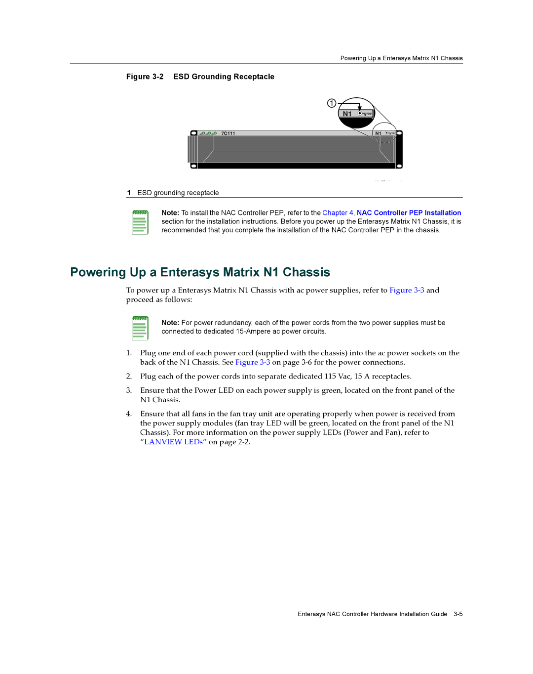
Figure 3-2 ESD Grounding Receptacle
1
N1
GROUND STRAP
7C111 | N1 |
N1 7C111 | d |
1ESD grounding receptacle
Note: To install the NAC Controller PEP, refer to the Chapter 4, NAC Controller PEP Installation section for the installation instructions. Before you power up the Enterasys Matrix N1 Chassis, it is recommended that you complete the installation of the NAC Controller PEP in the chassis.
Powering Up a Enterasys Matrix N1 Chassis
To power up a Enterasys Matrix N1 Chassis with ac power supplies, refer to Figure 3‐3 and proceed as follows:
Note: For power redundancy, each of the power cords from the two power supplies must be connected to dedicated
1.Plug one end of each power cord (supplied with the chassis) into the ac power sockets on the back of the N1 Chassis. See Figure 3‐3 on page 3‐6 for the power connections.
2.Plug each of the power cords into separate dedicated 115 Vac, 15 A receptacles.
3.Ensure that the Power LED on each power supply is green, located on the front panel of the N1 Chassis.
4.Ensure that all fans in the fan tray unit are operating properly when power is received from the power supply modules (fan tray LED will be green, located on the front panel of the N1 Chassis). For more information on the power supply LEDs (Power and Fan), refer to “LANVIEW LEDs” on page 2‐2.
Enterasys NAC Controller Hardware Installation Guide