Setting Up the Enterasys Matrix N1 Chassis
Table
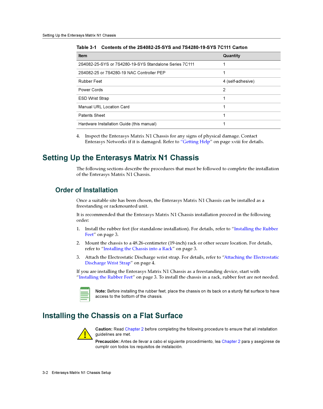
Item | Quantity |
|
|
1 | |
|
|
1 | |
|
|
Rubber Feet | 4 |
|
|
Power Cords | 2 |
|
|
ESD Wrist Strap | 1 |
|
|
Manual URL Location Card | 1 |
|
|
Patents Sheet | 1 |
|
|
Hardware Installation Guide (this manual) | 1 |
|
|
4.Inspect the Enterasys Matrix N1 Chassis for any signs of physical damage. Contact Enterasys Networks if it is damaged. Refer to “Getting Help” on page xviii for details.
Setting Up the Enterasys Matrix N1 Chassis
The following sections describe the procedures that must be followed to complete the installation of the Enterasys Matrix N1 Chassis.
Order of Installation
Once a suitable site has been chosen, the Enterasys Matrix N1 Chassis can be installed as a freestanding or rackmounted unit.
It is recommended that the Enterasys Matrix N1 Chassis installation proceed in the following order:
1.Install the rubber feet (for standalone installation). For details, refer to “Installing the Rubber Feet” on page 3.
2.Mount the chassis to a 48.26‐centimeter (19‐inch) rack or other secure location. For details, refer to “Installing the Chassis into a Rack” on page 3.
3.Attach the Electrostatic Discharge wrist strap. For details, refer to “Attaching the Electrostatic Discharge Wrist Strap” on page 4.
If you are installing the Enterasys Matrix N1 Chassis as a freestanding device, start with
“Installing the Rubber Feet” on page 3. To install the chassis in a rack, rubber feet are not needed.
Note: Before installing the rubber feet, place the chassis on its back on a sturdy flat surface to have access to the bottom of the chassis.
Installing the Chassis on a Flat Surface
Caution: Read Chapter 2 before completing the following procedure to ensure that all installation guidelines are met.
Precaución: Antes de llevar a cabo el siguiente procedimiento, lea Chapter 2 para y asegúrese de cumplir con todos los requisitos de instalación.