Completing the Installation
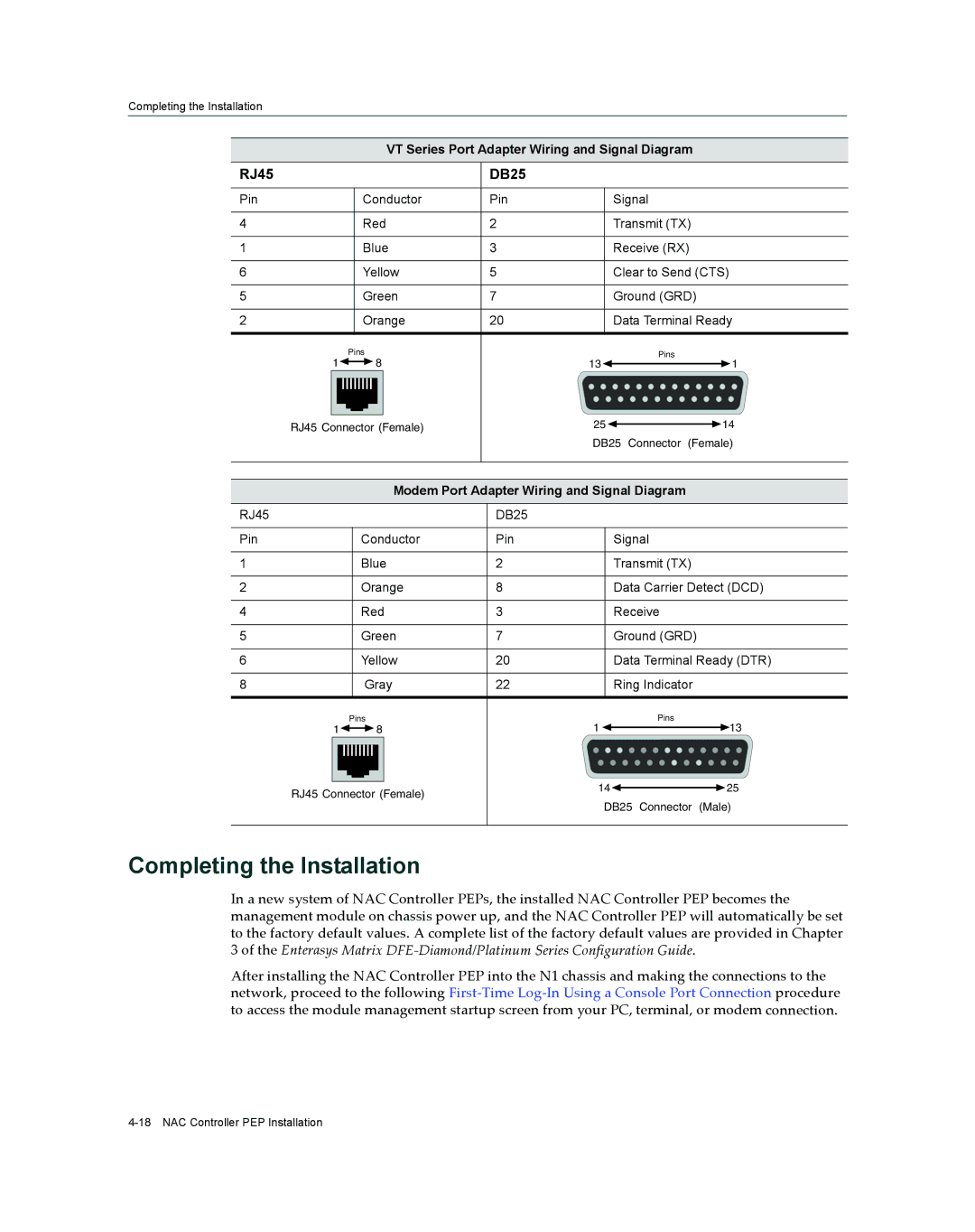
VT Series Port Adapter Wiring and Signal Diagram
RJ45 |
| DB25 |
| |
Pin | Conductor | Pin | Signal | |
4 | Red | 2 | Transmit (TX) | |
1 | Blue | 3 | Receive (RX) | |
6 | Yellow | 5 | Clear to Send (CTS) | |
5 | Green | 7 | Ground (GRD) | |
2 | Orange | 20 | Data Terminal Ready | |
| Pins |
| Pins | |
1 | 8 | 13 | 1 | |
RJ45 Connector (Female) | 25 | 14 | ||
|
| DB25 Connector (Female) | ||
| Modem Port Adapter Wiring and Signal Diagram | |||
RJ45 |
| DB25 |
| |
Pin | Conductor | Pin | Signal | |
1 | Blue | 2 | Transmit (TX) | |
2 | Orange | 8 | Data Carrier Detect (DCD) | |
4 | Red | 3 | Receive | |
5 | Green | 7 | Ground (GRD) | |
6 | Yellow | 20 | Data Terminal Ready (DTR) | |
8 | Gray | 22 | Ring Indicator | |
| Pins |
| Pins | |
1 | 8 | 1 | 13 | |
RJ45 Connector (Female) | 14 | 25 | ||
DB25 Connector (Male) | ||||
|
| |||
Completing the Installation
In a new system of NAC Controller PEPs, the installed NAC Controller PEP becomes the management module on chassis power up, and the NAC Controller PEP will automatically be set to the factory default values. A complete list of the factory default values are provided in Chapter
3of the Enterasys Matrix DFE‐Diamond/Platinum Series Configuration Guide.
After installing the NAC Controller PEP into the N1 chassis and making the connections to the network, proceed to the following First‐Time Log‐In Using a Console Port Connection procedure to access the module management startup screen from your PC, terminal, or modem connection.