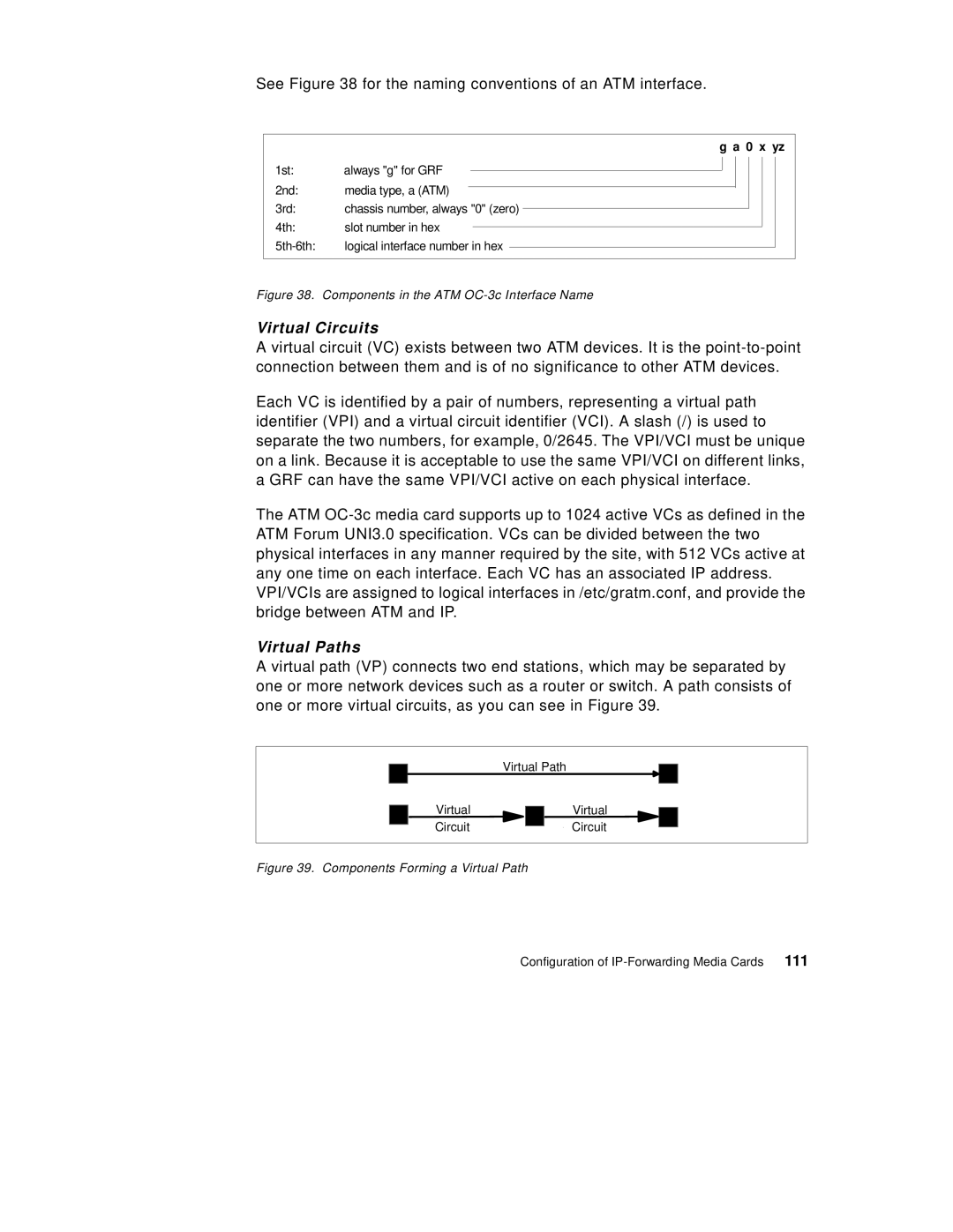
See Figure 38 for the naming conventions of an ATM interface.
g a 0 x yz
1st: | always "g" for GRF |
|
|
|
|
|
|
|
| |
|
|
|
|
|
|
|
| |||
2nd: | media type, a (ATM) |
|
|
|
|
|
|
|
|
|
|
|
|
|
|
|
|
|
| ||
3rd: | chassis number, always "0" (zero) |
|
|
|
|
| ||||
|
|
|
|
| ||||||
4th: | slot number in hex |
|
|
|
|
|
| |||
|
|
|
|
|
| |||||
logical interface number in hex |
|
|
|
|
| |||||
|
|
|
|
| ||||||
Figure 38. Components in the ATM OC-3c Interface Name
Virtual Circuits
Avirtual circuit (VC) exists between two ATM devices. It is the
Each VC is identified by a pair of numbers, representing a virtual path identifier (VPI) and a virtual circuit identifier (VCI). A slash (/) is used to separate the two numbers, for example, 0/2645. The VPI/VCI must be unique on a link. Because it is acceptable to use the same VPI/VCI on different links, a GRF can have the same VPI/VCI active on each physical interface.
The ATM
Virtual Paths
A virtual path (VP) connects two end stations, which may be separated by one or more network devices such as a router or switch. A path consists of one or more virtual circuits, as you can see in Figure 39.
Virtual Path
Virtual Circuit
Virtual Circuit
Figure 39. Components Forming a Virtual Path
Configuration of | 111 |