Chapter 5. Single RS/6000 SP and Single SP Switch Router
This section provides several sample configurations that are possible with a single RS/6000 SP and a single SP Switch Router. Sample configurations range from using the SP Switch Router as a conventional high performance router up to the connection of two SP partitions, allowing
5.1 Single SP Partition and Single SP Switch Router Adapter Card
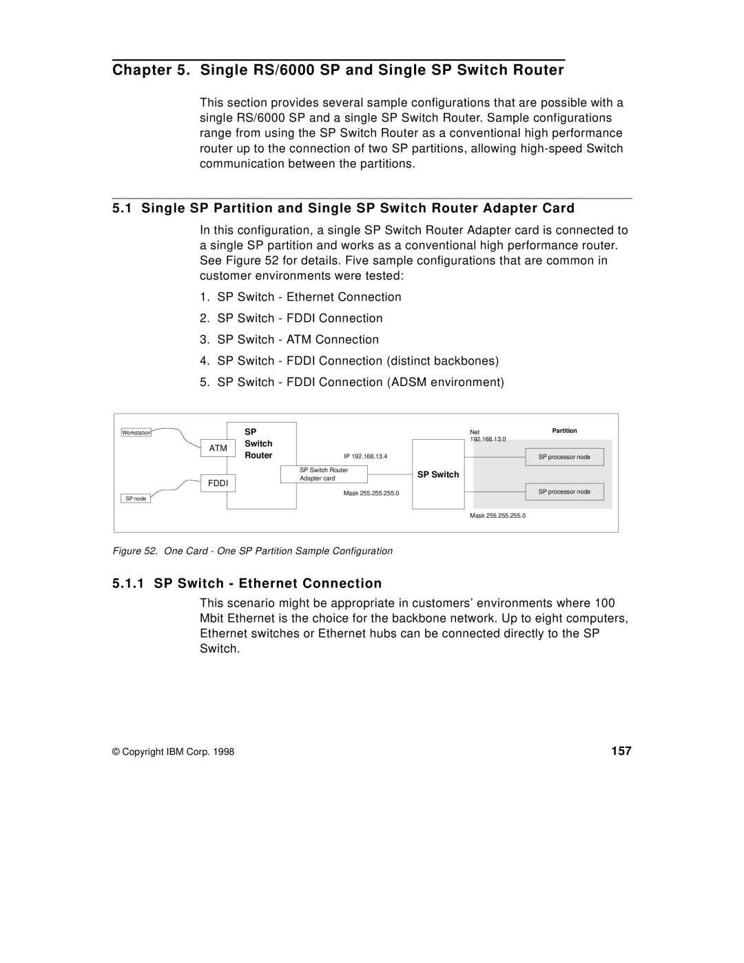
In this configuration, a single SP Switch Router Adapter card is connected to a single SP partition and works as a conventional high performance router. See Figure 52 for details. Five sample configurations that are common in customer environments were tested:
1.SP Switch - Ethernet Connection
2.SP Switch - FDDI Connection
3.SP Switch - ATM Connection
4.SP Switch - FDDI Connection (distinct backbones)
5.SP Switch - FDDI Connection (ADSM environment)
Workstation |
| SP |
| Net | Partition |
|
| Switch |
| 192.168.13.0 |
|
| ATM |
|
|
| |
| Router | IP 192.168.13.4 |
|
| |
|
|
| SP processor node | ||
|
|
| SP Switch Router | SP Switch |
|
| FDDI |
| Adapter card |
| |
|
|
|
| ||
|
|
|
|
| |
SP node |
|
| Mask 255.255.255.0 |
| SP processor node |
|
|
|
|
| |
|
|
|
| Mask 255.255.255.0 |
|
Figure 52. One Card - One SP Partition Sample Configuration
5.1.1 SP Switch - Ethernet Connection
This scenario might be appropriate in customers’ environments where 100 Mbit Ethernet is the choice for the backbone network. Up to eight computers, Ethernet switches or Ethernet hubs can be connected directly to the SP Switch.
© Copyright IBM Corp. 1998 | 157 |