5.2.2 Complex Configuration
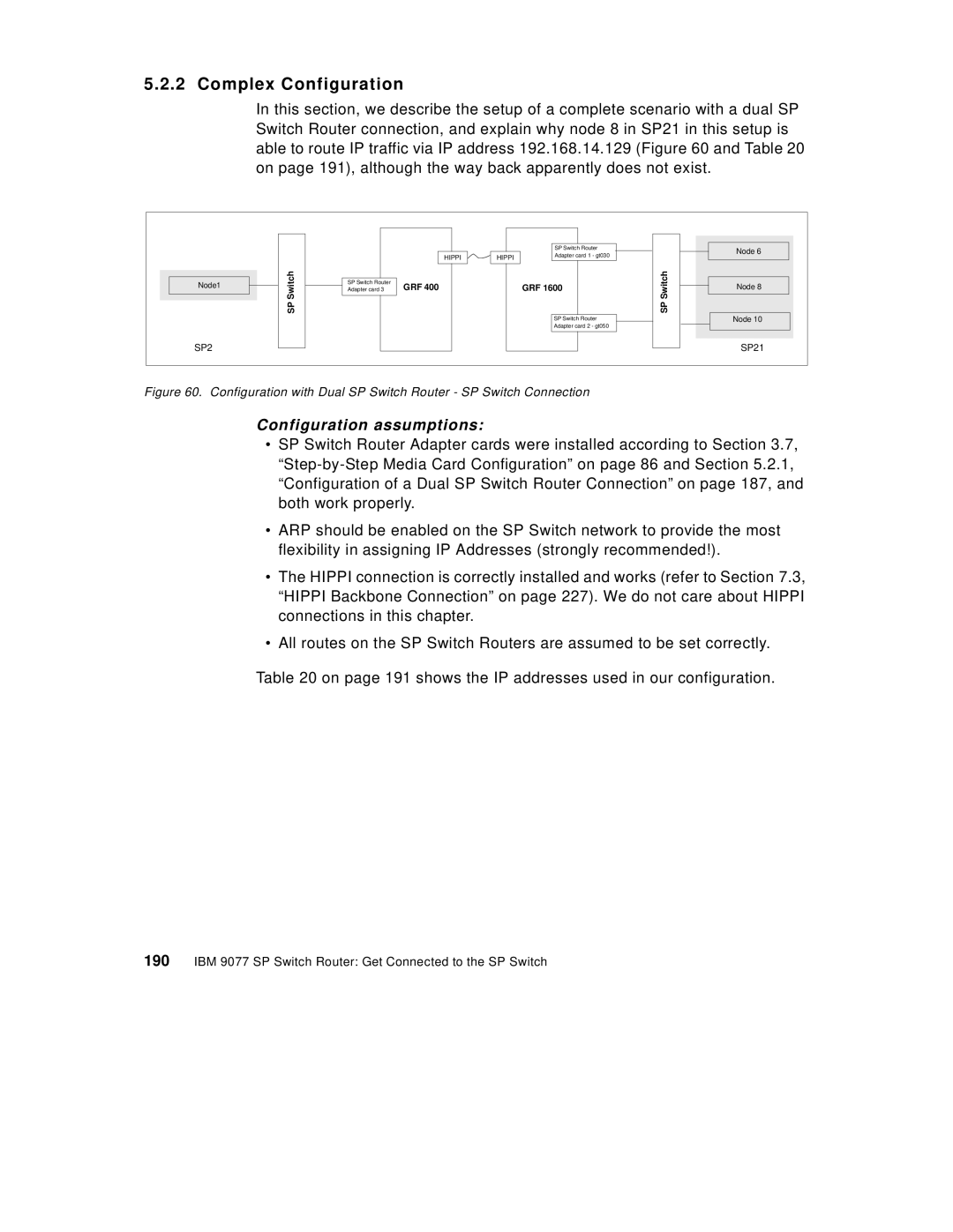
In this section, we describe the setup of a complete scenario with a dual SP Switch Router connection, and explain why node 8 in SP21 in this setup is able to route IP traffic via IP address 192.168.14.129 (Figure 60 and Table 20 on page 191), although the way back apparently does not exist.
|
|
|
|
| SP Switch Router |
| Node 6 |
|
|
| HIPPI | HIPPI | Adapter card 1 - gt030 |
| |
|
|
|
|
| |||
| h |
|
|
|
| Switch |
|
| c | SP Switch Router |
|
|
|
| |
Node1 | t | GRF 400 |
|
| Node 8 | ||
i |
| GRF 1600 | |||||
w | Adapter card 3 |
| |||||
| S |
|
|
|
|
| |
| P |
|
|
|
| SP |
|
| S |
|
|
| SP Switch Router | Node 10 | |
|
|
|
|
|
| ||
|
|
|
|
| Adapter card 2 - gt050 |
|
|
SP2 |
|
|
|
|
|
| SP21 |
Figure 60. Configuration with Dual SP Switch Router - SP Switch Connection
Configuration assumptions:
•SP Switch Router Adapter cards were installed according to Section 3.7,
•ARP should be enabled on the SP Switch network to provide the most flexibility in assigning IP Addresses (strongly recommended!).
•The HIPPI connection is correctly installed and works (refer to Section 7.3, “HIPPI Backbone Connection” on page 227). We do not care about HIPPI connections in this chapter.
•All routes on the SP Switch Routers are assumed to be set correctly.
Table 20 on page 191 shows the IP addresses used in our configuration.