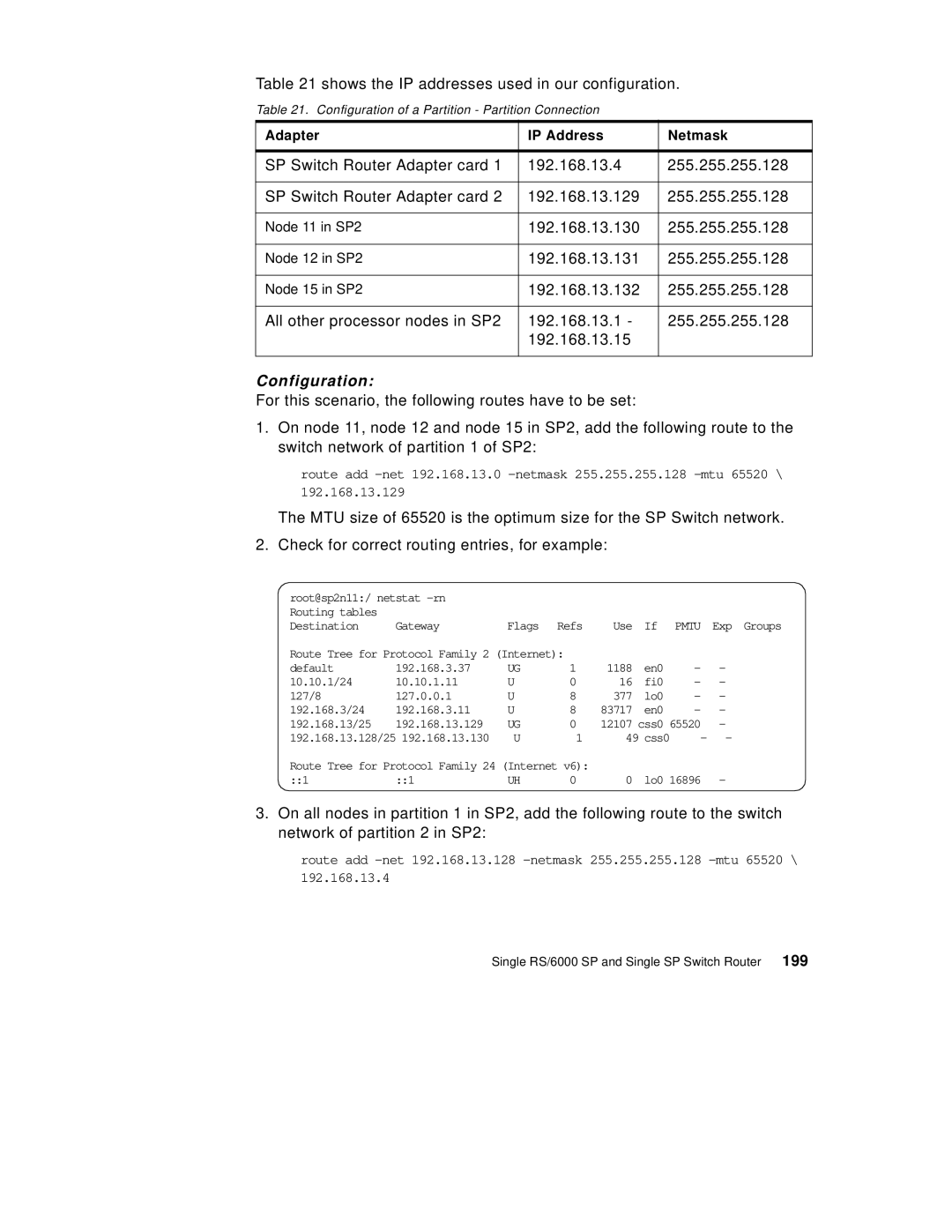
Table 21 shows the IP addresses used in our configuration.
Table 21. Configuration of a Partition - Partition Connection
Adapter | IP Address | Netmask |
|
|
|
SP Switch Router Adapter card 1 | 192.168.13.4 | 255.255.255.128 |
|
|
|
SP Switch Router Adapter card 2 | 192.168.13.129 | 255.255.255.128 |
|
|
|
Node 11 in SP2 | 192.168.13.130 | 255.255.255.128 |
|
|
|
Node 12 in SP2 | 192.168.13.131 | 255.255.255.128 |
|
|
|
Node 15 in SP2 | 192.168.13.132 | 255.255.255.128 |
|
|
|
All other processor nodes in SP2 | 192.168.13.1 - | 255.255.255.128 |
| 192.168.13.15 |
|
|
|
|
Configuration:
For this scenario, the following routes have to be set:
1.On node 11, node 12 and node 15 in SP2, add the following route to the switch network of partition 1 of SP2:
route add
192.168.13.129
The MTU size of 65520 is the optimum size for the SP Switch network.
2. Check for correct routing entries, for example:
root@sp2n11:/ netstat |
|
|
|
|
|
| |
Routing tables |
|
|
|
|
|
|
|
Destination | Gateway | Flags | Refs | Use | If | PMTU | Exp Groups |
Route Tree for Protocol Family 2 (Internet): |
|
|
|
| |||
default | 192.168.3.37 | UG | 1 | 1188 | en0 | - | - |
10.10.1/24 | 10.10.1.11 | U | 0 | 16 | fi0 | - | - |
127/8 | 127.0.0.1 | U | 8 | 377 | lo0 | - | - |
192.168.3/24 | 192.168.3.11 | U | 8 | 83717 | en0 | - | - |
192.168.13/25 | 192.168.13.129 | UG | 0 | 12107 | css0 65520 | - | |
192.168.13.128/25 192.168.13.130 | U | 1 | 49 css0 | - | - | ||
Route Tree for Protocol Family 24 (Internet v6): |
|
|
|
| |||
::1 | ::1 | UH | 0 | 0 | lo0 16896 | - | |
3.On all nodes in partition 1 in SP2, add the following route to the switch network of partition 2 in SP2:
route add
192.168.13.4
