Table 14. Configuration of SP Switch - Ethernet Connection
Adapter | IP Address |
|
|
Ethernet interface in F50 (en0 on ent0) | 10.20.30.50 |
|
|
SP Switch Router Ethernet media card | 10.20.30.1 |
(port 1) |
|
|
|
SP Switch Router Adapter card 1 | 192.168.14.4 |
|
|
SP processor nodes in SP21 | 192.168.14.1 - 192.168.14.15 |
|
|
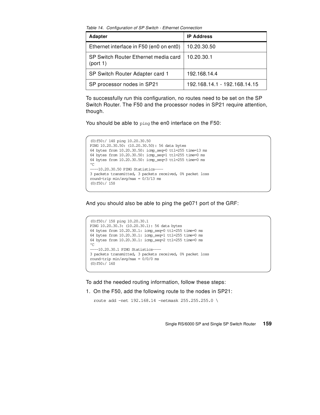
To successfully run this configuration, no routes need to be set on the SP Switch Router. The F50 and the processor nodes in SP21 require attention, though.
You should be able to ping the en0 interface on the F50:
(0)f50:/ 14$ ping 10.20.30.50
PING 10.20.30.50: (10.20.30.50): 56 data bytes
64 bytes from 10.20.30.50: icmp_seq=0 ttl=255 time=13 ms
64 bytes from 10.20.30.50: icmp_seq=1 ttl=255 time=0 ms
64 bytes from 10.20.30.50: icmp_seq=3 ttl=255 time=0 ms ^C
3 packets transmitted, 3 packets received, 0% packet loss
(0)f50:/ 15$
And you should also be able to ping the ge071 port of the GRF:
(0)f50:/ 15$ ping 10.20.30.1
PING 10.20.30.3: (10.20.30.1): 56 data bytes
64 bytes from 10.20.30.1: icmp_seq=0 ttl=255 time=0 ms
64 bytes from 10.20.30.1: icmp_seq=1 ttl=255 time=0 ms
64 bytes from 10.20.30.1: icmp_seq=2 ttl=255 time=0 ms ^C
3 packets transmitted, 3 packets received, 0% packet loss
(0)f50:/ 16$
To add the needed routing information, follow these steps:
1.On the F50, add the following route to the nodes in SP21: route add
Single RS/6000 SP and Single SP Switch Router 159
