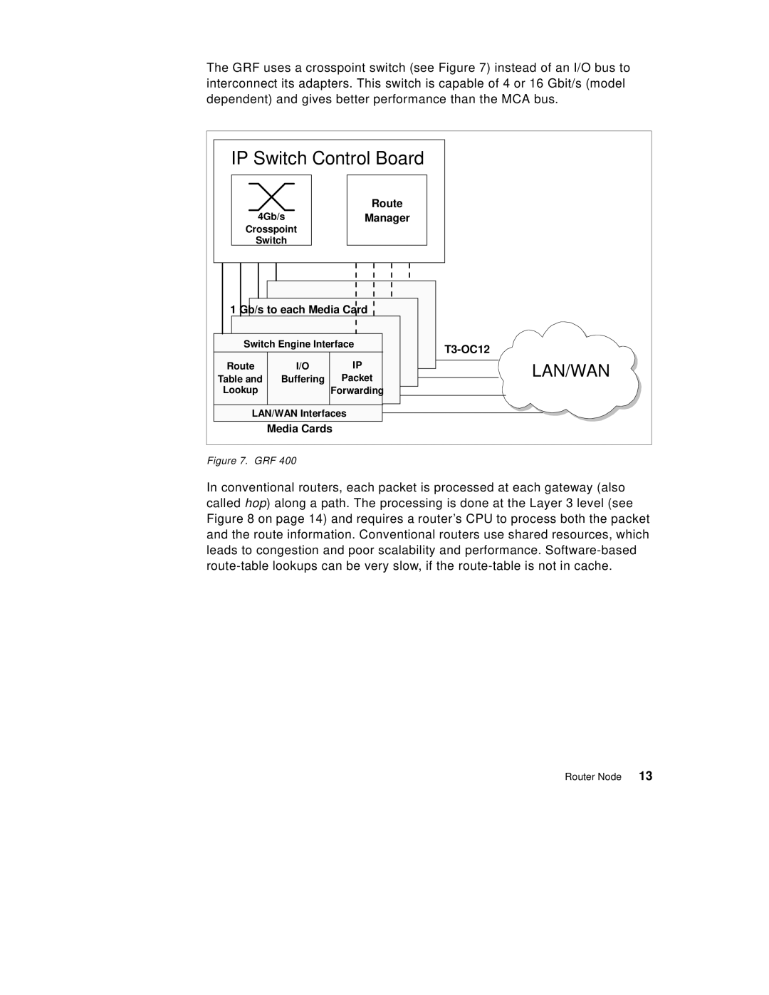
The GRF uses a crosspoint switch (see Figure 7) instead of an I/O bus to interconnect its adapters. This switch is capable of 4 or 16 Gbit/s (model dependent) and gives better performance than the MCA bus.
IP Switch Control Board |
| |||
|
| Route |
| |
4Gb/s | Manager |
| ||
Crosspoint |
|
| ||
Switch |
|
| ||
1 Gb/s to each Media Card |
| |||
Switch Engine Interface | ||||
|
|
| ||
Route | I/O | IP | LAN/WAN | |
Table and | Buffering | Packet | ||
| ||||
Lookup |
| Forwarding |
| |
LAN/WAN Interfaces |
| |||
| Media Cards |
| ||
Figure 7. GRF 400
In conventional routers, each packet is processed at each gateway (also called hop) along a path. The processing is done at the Layer 3 level (see Figure 8 on page 14) and requires a router’s CPU to process both the packet and the route information. Conventional routers use shared resources, which leads to congestion and poor scalability and performance.
Router Node 13