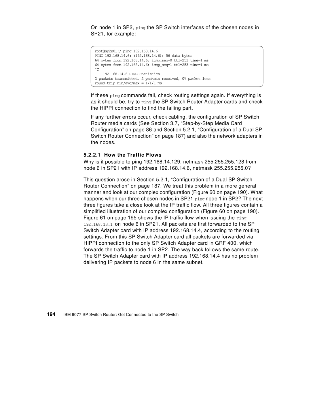
On node 1 in SP2, ping the SP Switch interfaces of the chosen nodes in SP21, for example:
root@sp2n01:/ ping 192.168.14.6
PING 192.168.14.6: (192.168.14.6): 56 data bytes
64 bytes from 192.168.14.6: icmp_seq=0 ttl=253 time=1 ms
64 bytes from 192.168.14.6: icmp_seq=1 ttl=253 time=1 ms ^C
2 packets transmitted, 2 packets received, 0% packet loss
If these ping commands fail, check routing settings again. If everything is as it should be, try to ping the SP Switch Router Adapter cards and check the HIPPI connection to find the failing part.
If any further errors occur, check cabling, the configuration of SP Switch Router media cards (See Section 3.7,
5.2.2.1 How the Traffic Flows
Why is it possible to ping 192.168.14.129, netmask 255.255.255.128 from node 6 in SP21 with IP address 192.168.14.6, netmask 255.255.255.0?
This question arose in Section 5.2.1, “Configuration of a Dual SP Switch Router Connection” on page 187. We treat this problem in a more general manner and look at our complex configuration (Figure 60 on page 190). What happens when our three chosen nodes in SP21 ping node 1 in SP2? The next three figures take a close look at the IP traffic flow. All three figures contain a simplified illustration of our complex configuration (Figure 60 on page 190). Figure 61 on page 195 shows the IP traffic flow when issuing the ping 192.168.13.1 on node 6 in SP21. All packets are first forwarded to the SP Switch Adapter card with IP address 192.168.14.4, according to the routing settings. From this SP Switch Adapter card all packets are forwarded via HIPPI connection to the only SP Switch Adapter card in GRF 400, which forwards the traffic to node 1 in SP2. The way back follows the same route. The SP Switch Adapter card with IP address 192.168.14.4 has no problem delivering IP packets to node 6 in the same subnet.