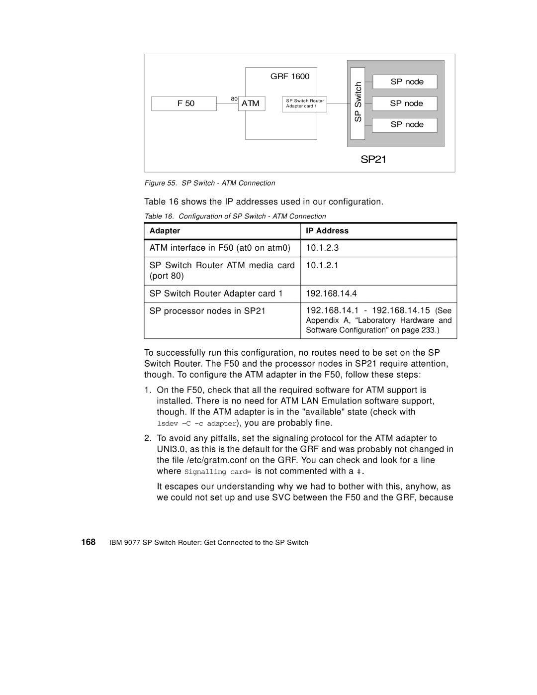
F 50
80ATM
GRF 1600
SP Switch Router
Adapter card 1
|
|
|
|
|
|
|
|
|
|
| Switch |
| SP node |
|
|
|
| ||
|
|
|
| |
|
| |||
SP node |
| |||
|
|
| ||
| SP |
|
|
|
|
| |||
SP node |
| |||
|
|
|
| |
|
|
|
| |
|
|
|
|
|
|
|
|
|
|
|
|
|
|
|
SP21
Figure 55. SP Switch - ATM Connection
Table 16 shows the IP addresses used in our configuration.
Table 16. Configuration of SP Switch - ATM Connection
Adapter | IP Address |
|
|
ATM interface in F50 (at0 on atm0) | 10.1.2.3 |
|
|
SP Switch Router ATM media card | 10.1.2.1 |
(port 80) |
|
|
|
SP Switch Router Adapter card 1 | 192.168.14.4 |
|
|
SP processor nodes in SP21 | 192.168.14.1 - 192.168.14.15 (See |
| Appendix A, “Laboratory Hardware and |
| Software Configuration” on page 233.) |
|
|
To successfully run this configuration, no routes need to be set on the SP Switch Router. The F50 and the processor nodes in SP21 require attention, though. To configure the ATM adapter in the F50, follow these steps:
1.On the F50, check that all the required software for ATM support is installed. There is no need for ATM LAN Emulation software support, though. If the ATM adapter is in the "available" state (check with lsdev
2.To avoid any pitfalls, set the signaling protocol for the ATM adapter to UNI3.0, as this is the default for the GRF and was probably not changed in the file /etc/gratm.conf on the GRF. You can check and look for a line where Signalling card= is not commented with a #.
It escapes our understanding why we had to bother with this, anyhow, as we could not set up and use SVC between the F50 and the GRF, because