IBM
1999
Law
Contents
Ripl Scsi ID
Diagnostics
AIX
PCI
ISA
Determination
Index
Commission FCC Statement
Communications Statements
European Union EU Statement
Safety Requirements
International Electrotechnical Commission IEC Statement
Avis
Ministère des
Electromagnetic Interference EMI Statement Taiwan
Vcci Statement
Following is a summary of the EMI Taiwan statement above
Radio Protection for Germany
Safety Notices
Electrical Safety
Shock Hazard Disconnect the power cable from
Laser
Device. Do not attempt to
While
Drive As it
Xiv RS/6000 Enterprise Server Model H Series Users Guide
Battery Return Program
Environmental Notices
Product Recycling and Disposal
Environmental Design
Xvi RS/6000 Enterprise Server Model H Series Users Guide
About This Book
ISO
Related Publications
Following publications are available
Trademarks
System Description
Processors
8GB
Using
System Unit
Starting the System Unit
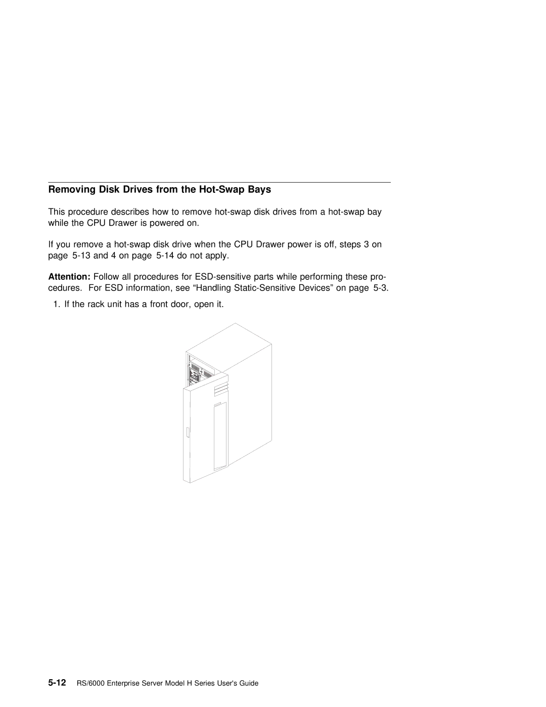
Open the front door of the 7014 Model S00 Rack
Progress Codes Appear Operator Panel display Power
Power on self test During
Not flash
Stopping the System Unit
Reading the Operator Panel Display
During power Self Test
Post
Using the Keyboards
Function Keys
6RS/6000 Enterprise Server Model H Series Users Guide
Three-Button Mouse
Using
Moving around in your document much easier
Has Cable That Plugs Into Mouse Connector Rear System Unit
Correctly
Caring for the Mouse
Cleaning the Mouse
Using the 3.5-Inch Diskette Drive Diskette Compatibility
Write-Protecting 3.5-Inch Diskettes
Loading and Unloading the 3.5-Inch Diskette
Using the CD-ROM Drive
Class Laser
Not Attempt
Device Not
Loading the CD-ROM Drive
CD-ROM Drive
Drive
Push Hold Unload Button Until the drawer Comes Out Then
Emergency Eject
Disk Drives
Physical
Hot Swap Disk Drive Physical Locations
Handling Guidelines
Labels
Disk Drive Status LED States Scsi Disk Drives
Following table explains the meaning of the green
Amber status LEDs and spin down button
Status LEDs
Following table explains the meaning of the Power, Ready
SSA Disk Drives
Check status LEDs
Status Definition
Processor Menus
Chapter
Processor
Menus Service Graphics Ascii ter Aids Terminals Minals
Ascii or
Service Processor Menus
Access Service Processor menus locally
Menu Inactivity
Menus remotely
Power-On System
Allows the user to power-on the system
Menus
User
Read Progress Indicators from Last System Boot
Read Service Processor Error Logs
Read System Post Errors
GMT. AIX
Privileged User Menus
Main Menu
System Name Main Menu
Service Processor Setup Menu
Passwords
Change Privileged Access Password
Change General Access Password
Menu Access Password
Enable/Disable Console Mirroring
Start Talk Mode
Surveillance Setup Menu
Surveillance Delay
Reset
Surveillance
System Power Control Menu
Enable/Disable Unattended Start Mode
Ring Indicator Power-On Menu
Defaults are
Power on System
Power off System
Read VPD Image from Last System Boot
System Information Menu
Power-On Se
Errors if
Displays Non-Volatile Random Access Memory Nvram content
Cient working System Resources
Service Processor3-15Menus
Call-in/Call-out Setup Menu
Ring Indicate Power-On Menu
Menu
First two lines
Serial Port Selection Menu
Serial Port Speed Setup Menu
Telephone Number Setup Menu
Administration Center computer catcher that receives probl
From Servers. Contact Your System Administrator For Correct
Enter here. Until You Have That Number Leave this
Digital
Call-Out Policy Setup Menu
PIN
This Field as Following Example
Call out to one of the following
Setup
Password
Retries
UserID
Policy Setup Menu
Reboot
Restart policy
After a System
Service Processor Functions and Features
Enable
Restart
Set Use
Ties Phone Numbers Language
System Power-On Methods
Operating system Set Enable a
Sessions From Service Processor Opera
Start Mode
Process
Service Processor Reboot/Restart Recovery
Operation
Restart Policy
Use
Policy
Provides the Service Processor with a means
Service Processor System Monitoring Surveillance
Surveillance
Call Out Call-Home
System Configuration
Console Mirroring
Service Processor Firmware Updates
This Service Aid Only Supported
Find Out Name Update Image File. This Service
Login Prompt. After System
Requires User assistance, it Requested
Service
Error Log
Logs
System Post Errors
If Post Power-On Self Test errors occur during
System Management Services
Graphical System Management Services
Command
System Management Services4-3
Config
System Management Services4-5
MultiBoot
Doc
System Management Services4-7
Install From
ToInstalltheFrom
DriveFor
Icon Then Select
Save
Error Log
Utilities
Remote Initial
Password
Load
Locked Position Power-on Password Not Set Icon
ReturnsRemotetoOff
14RS/6000 Enterprise Server Model H Series Users Guide
Hard Disk Spin Up Delay
Error Log
Ripl
Than 0 to 255, an error Message Is displayed When You Select
Ping icon allows you to confirm that a specified address is
20RS/6000 Enterprise Server Model H Series Users Guide
Scsi ID
Update
Firmware image Being copied into your syste
You
Not turn off the system unit. Turning
System Firmware Recovery
Text-Based System Management Services
Display Configuration
MultiBoot Menu
Boot
Select Boot Devices
Scsi CD-ROM
Access to Following options
Set Password Unattended Start Mode
Entering this selection permits
Set
Setup
Word
System Management Services4-31
Media Type
Ping
Hard Disk Spin Up Delay
Screen similar to the following is displayed when you select
This Option. You Can view or clear your computers error log
This option allows you to update your system
Firmware
This option allows you to view and change the addresses
Scsi
See Service Processor Firmware
Updates For Details about updating the service pr
Open Firmware Command Prompt
Installing Options
Safety Considerations
Handling Static-Sensitive Devices
Expansion Bays
Drives Banks However, a
Disk Drive
Bays
Preinstallation Steps All Bays
Disk Drive Bank Install
Disk Drive Bank Remove
Disk Drive From bank Remove
Bays
Drives into
CPU
Installing Options5-7
For the first time, you must
If you Are installing Drives
SSA Disk Drives
Installing Options5-9
Scsi Disk
LED or Button Status Definition
Following Explains Meaning Power Ready
Drives
Disk
Installing Options5-13
Scsi Disk Drives SSA Disk Drives
Installing Options5-15
16RS/6000 Enterprise Server Model H Series Users Guide
Using
Standalone and Online Diagnostics Operating Considerations
Identifying the Terminal Type to Diagnostics
Standalone Diagnostics
Running Standalone Diagnostics
Running Online Diagnostics
Resetting
Defi
Running the Diagnostics from a TTY Terminal
Always
11/31/41 51/61 Settings
3151 3161/3164
Setup 3151 3161/3164
Attributes 11/31/41 51/61 Settings
11/31/41 51/61 Settings Attributes
Additional Communication Attributes
Additional Keyboard Attributes
Setup 31/41 51/61 3164 Attributes Settings
Keyboard 3151/11 3161
Additional Printer Attributes
31/41 51/61 3164 Attributes Settings
3151/11 3161 Description
Online Diagnostics Modes of Operation
Service Mode
Running the Online Diagnostics in Service Mode
Service Mode Provides
Concurrent Mode
Diagnostic
Key from a defined terminal produces Confirm
Share-test
Running the Online Diagnostics in Concurrent Mode
Running the Online Diagnostics in Maintenance Mode
Ating
Enter the shutdown -m
Standalone Diagnostic Operation
Running the Standalone Diagnostics
Remove All Tapes Diskettes CD-ROMs Insert Diagnostic
Then press the F3 key again to return
Codes
Location Codes
Contr
AIX Location Codes
AB-CD-EF-G,H
AB-CD-EF-GH
Memory module in system board slot
Location code is Defined as
Memory module 12 in card in system board slot
Pluggable PCI adapters
Integrated ISA adapters
Non-integrated ISA Adapters Model 50 only
Device Attached Scsi controller
AIX and Physical Location Code Reference Table Model
Using the Online and Standalone Diagnostics6-19
FRU Name
Location Code
Central
Board
Physical
Identification
Connection
Fans
Physical Logical FRU Name
Panel
AIX
AIX
System Planar
Scsi Devices
PCI Scsi
Through Where G identi-through B2.6 Nector Bus
Code
Card
32RS/6000 Enterprise Server Model H Series Users Guide
Using the Service Aids
VPD
PCI RAID
Introduction to Service Aids
Following are descriptions of the service aids
This Service Aid Allows Access
Aid the user must know Root Password when a Has Bee Lished
Aid
Admi
On Policy
Configure Surveillance Policy Service Aid
Configure Reboot Policy Service Aid
8RS/6000 Enterprise Server Model H Series Users Guide
Save or Restore Hardware Management Policies Service Aid
Diagnostic Package Utility Service Aid
/etc/lpp/diagnostics/data/hmpolicies file
Contents of/etc/lpp/diagnostics/data/hmpolicies the file
Disk
Dials and Lpfk Configuration Service Aid
Aids
Using the Service7-11Aids
Disk Maintenance Service Aid
Disk Service Aids
Diskette
Display/Alter
Optical
Configuration Service Aid and Display Configuration
Data Task
List Task
Display Vital
Add or Delete Drawer Configuration Task
Change Hardware Vital Product Data Task
Add Resource to Resource List Task
Delete Resource from Resource List Task
Display and Change Diagnostic Test List Service Aid
Display Previous Diagnostic Results Service Aid
To repo
Dat
Display Test Patterns Service Aid
Scsi Display Configuration Service Aid
Generic Microcode Download Service Aid
LAN
Service Aid
Machine Check Error Log Service Aid
Periodic Diagnostics Service Aid
Microcode Download Service Aid
Scsi Bus Analyzer Task
Scsi
Service Hints Service Aid
Utilities Service Aid
Tape
Update System or Service Processor Flash Service Aid
Login prompt. After the system
Display Firmware Device Node
Display Resource Attributes
RAIDant Array Service Aid
PCI RAID Physical Disk Identify
SSA Location Code Format
Loops
Disk Drive Modules System unit are connected through t
Disk
Adapter t
Loop.
Cables Provide
Identification
Pdisks, Hdisks, Disk
Rules for SSA Loops
All Devices That Are Attached
Data
Adapter Card Are Connected Thro Links.
Disk Drive Module Slot Isolated from the SSA Adapter
Link
SSA Service Aids
Verification
Starting the SSA Service Aids
Identify Function
32RS/6000 Enterprise Server Model H Series Users Guide
Set
Set Service Mode service Aid enables You Determine
For Identifi
Columns Information Displayed
Aids
Menu Have Following meanings
11111111
Using the Service7-35Aids
36RS/6000 Enterprise Server Model H Series Users Guide
Using the Service7-37Aids
Link Verification Service Aid
Power
Pdisk9
Through
A1 A2
?????
One SSA path is active. Also
Question Marks Show Where
Configuration Verification Service Aid
Select Hdisk Pdisk That You Want Test List Pdisks Displayed
You Select Pdisk List Hdisks Displayed
Disk service aid formats SSA disk drive modules
Formatting a disk drive module destroys all the data on
44RS/6000 Enterprise Server Model H Series Users Guide
Certify
46RS/6000 Enterprise Server Model H Series Users Guide
Model H Series Installation and Service. Guide
Link Verification Service Aid 7-38. Following Examples
Adapter. Five Disk Drive Mod Are Connected Connectors
Vari
Loops Associated information That Displayed Link Verif Aid
Scroll Display See All Connected Disk Drive
Example 2. Broken Loop Cable Removed
Using the Service7-51Aids
Adapter Normal loop
Using the Service7-53Aids
Finding the Device When Service Aids Are Available
Finding the Physical Location of a Device
Available
Link From Disk Drive Module Adapter Increas
Microcode Maintenance
Vital Product Data VPD
Using the System Verification Procedure
Considerations before Running This Procedure
Loading the Diagnostics
Running System Verification
Additional System Verification
Step
Hardware Problem Determination
This Procedure
Are the Online Diagnostics installed on this system?
Step
Page
Obvious
Display
Following steps to Shut
Did
Diagnostics loaded correctly Press the Enter key
Type Action
System Response Action
Did the Diagnostic Selection Menu display?
Diagnostics
Ter
Your Software support center
Problem Determination When Unable to Load Diagnostics
Did the diagnostics load?
E1EB
System does not respond When
Type Action
Disk Drive Module Power-On Self-Tests POSTs
SSA Problem Determination Procedures
Start Each time Module Switched
Adapter. The tests POST-1 and POST-2
Two Power-on Self-tests POSTs are Resident
Eprom
Record the Identification Numbers
Appendix A. System Records
Record and retain the following information
Device Records
Other
Might Have more preinstalled drives Than
C1 C2C3 C4 C5 C6
Adapter Location
Appendix B. Service Processor Setup and Test
Service Processor Setup Checklist
Testing the Setup
Call-In
Call-Out
Serial Port Configuration
Files
Appendix C
Modem Has Dip Switches Right Hand Side Unit. See
Your modem an IBM 7852-400? Yes Use
IBM
Public Network, so Phone Line Should Attach to
Setup F1 Rare
Recommended
Older Modems Not Respond
For More Information Some modems Such
Customizing the Modem Configuration Files
IBM 7852-400 DIP Switch Settings
Cfg
As a model to modify Find Necessary
Xon/Xoff Modems
Ring Detection
Terminal Emulators
Ripo
Seamless Transfer of a Modem Session
Recovery Procedures
DTR
Will do this. Watch for
Recovery Strategy
Prevention Strategy
Modem Configuration Samples Sample File modemm0.cfg
10RS/6000 Enterprise Server Model H Series Users Guide
# %R = paging number
Sample File modemm1.cfg
Appendix C. Modem Configurations-13
14RS/6000 Enterprise Server Model H Series Users Guide
# Componentname Espsetup Entry Service Processor Setup Z
Sample File modemz.cfg
16RS/6000 Enterprise Server Model H Series Users Guide
Appendix C. Modem Configurations-17
Sample File modemz0.cfg
18RS/6000 Enterprise Server Model H Series Users Guide
# Componentname Espsetup Entry Service Processor Setup F
Sample File modemf.cfg
20RS/6000 Enterprise Server Model H Series Users Guide
Appendix C. Modem Configurations-21
Sample File modemf0.cfg
RTS
Appendix C. Modem Configurations-23
24RS/6000 Enterprise Server Model H Series Users Guide
# Componentname Espsetup Entry Service Processor Setup F1
Sample File modemf1.cfg
26RS/6000 Enterprise Server Model H Series Users Guide
Appendix C. Modem Configurations-27
28RS/6000 Enterprise Server Model H Series Users Guide
Phases
Appendix D. Service
Pre-Standby Phase
SP Post
Bring-Up Phase
Standby Phase
LCD
Runtime Phase
4RS/6000 Enterprise Server Model H Series Users Guide
Adapter Adapter POSTs power-on
Configuration Verification service Aid
Index
GB,
Connector Disk Drive
SSA
Service Aids Support
Service Mode Configuration File Selection C-2
Network Information
Nvram
POS
Programmable Option Select 10-2
10-2 Programmable read-only memory
Disk Drive from Bank C or
10-1 Service Provider Sequence Startup Set
Inactive Connector Unavailable Link Vital Product Data
System description
SSA serial storage architecturecon System administrator
Stby
Voice Phone Number VPD vital Product Data
Vital Product Data Web sites Ergonomic information
Index
10RS/6000 Enterprise Server Model H Series Users Guide
Readers Comments Wed Like to Hear From You
Business Reply Mail
Page
IBM