Chapter
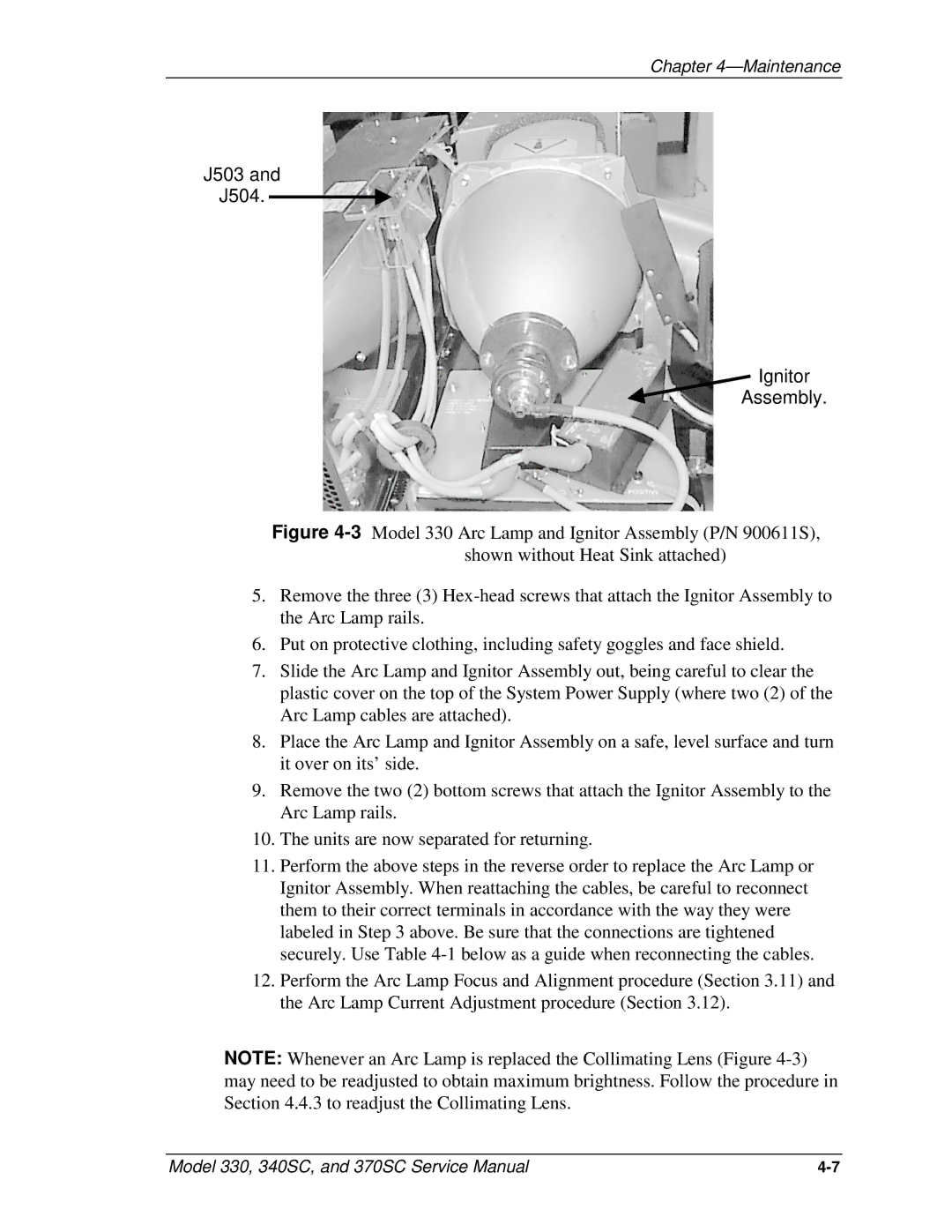
J503 and
J504.
Ignitor
Assembly.
Figure 4-3 Model 330 Arc Lamp and Ignitor Assembly (P/N 900611S), shown without Heat Sink attached)
5.Remove the three (3) Hex-head screws that attach the Ignitor Assembly to the Arc Lamp rails.
6.Put on protective clothing, including safety goggles and face shield.
7.Slide the Arc Lamp and Ignitor Assembly out, being careful to clear the plastic cover on the top of the System Power Supply (where two (2) of the Arc Lamp cables are attached).
8.Place the Arc Lamp and Ignitor Assembly on a safe, level surface and turn it over on its’ side.
9.Remove the two (2) bottom screws that attach the Ignitor Assembly to the Arc Lamp rails.
10.The units are now separated for returning.
11.Perform the above steps in the reverse order to replace the Arc Lamp or Ignitor Assembly. When reattaching the cables, be careful to reconnect them to their correct terminals in accordance with the way they were labeled in Step 3 above. Be sure that the connections are tightened securely. Use Table 4-1 below as a guide when reconnecting the cables.
12.Perform the Arc Lamp Focus and Alignment procedure (Section 3.11) and the Arc Lamp Current Adjustment procedure (Section 3.12).
NOTE: Whenever an Arc Lamp is replaced the Collimating Lens (Figure
Model 330, 340SC, and 370SC Service Manual |