Chapter
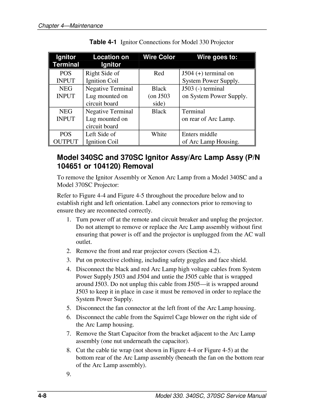
Table
Ignitor | Location on | Wire Color | Wire goes to: | |
Terminal | Ignitor |
|
| |
|
|
|
| |
POS | Right Side of | Red | J504 (+) terminal on | |
INPUT | Ignition Coil |
| System Power Supply. | |
NEG | Negative Terminal | Black | J503 | |
INPUT | Lug mounted on | (on J503 | on System Power Supply. | |
| circuit board | side) |
| |
NEG | Negative Terminal | Black | Terminal | |
INPUT | Lug mounted on |
| on rear of Arc Lamp. | |
| circuit board |
|
| |
POS | Left Side of | White | Enters middle | |
OUTPUT | Ignition Coil |
| of Arc Lamp Housing. | |
|
|
|
|
Model 340SC and 370SC Ignitor Assy/Arc Lamp Assy (P/N 104651 or 104120) Removal
To remove the Ignitor Assembly or Xenon Arc Lamp from a Model 340SC and a Model 370SC Projector:
Refer to Figure
1.Turn power off at the remote and circuit breaker and unplug the projector. Do not attempt to remove or replace the Arc Lamp assembly without first ensuring that power is off and the projector is unplugged from the AC wall outlet.
2.Remove the front and rear projector covers (Section 4.2).
3.Put on protective clothing, including safety goggles and face shield.
4.Disconnect the black and red Arc Lamp high voltage cables from System Power Supply J503 and J504 and untie the J505 cable that is wrapped around J503. Do not unplug this cable from
5.Disconnect the fan connector at the left front of the Arc Lamp housing.
6.Disconnect the cable from the Squirrel Cage blower on the right side of the Arc Lamp housing.
7.Remove the Start Capacitor from the bracket adjacent to the Arc Lamp assembly (one nut underneath the capacitor).
8.Cut the cable tie wrap (not shown in Figure
9.
Model 330. 340SC, 370SC Service Manual |