Chapter 3---Service Adjustments
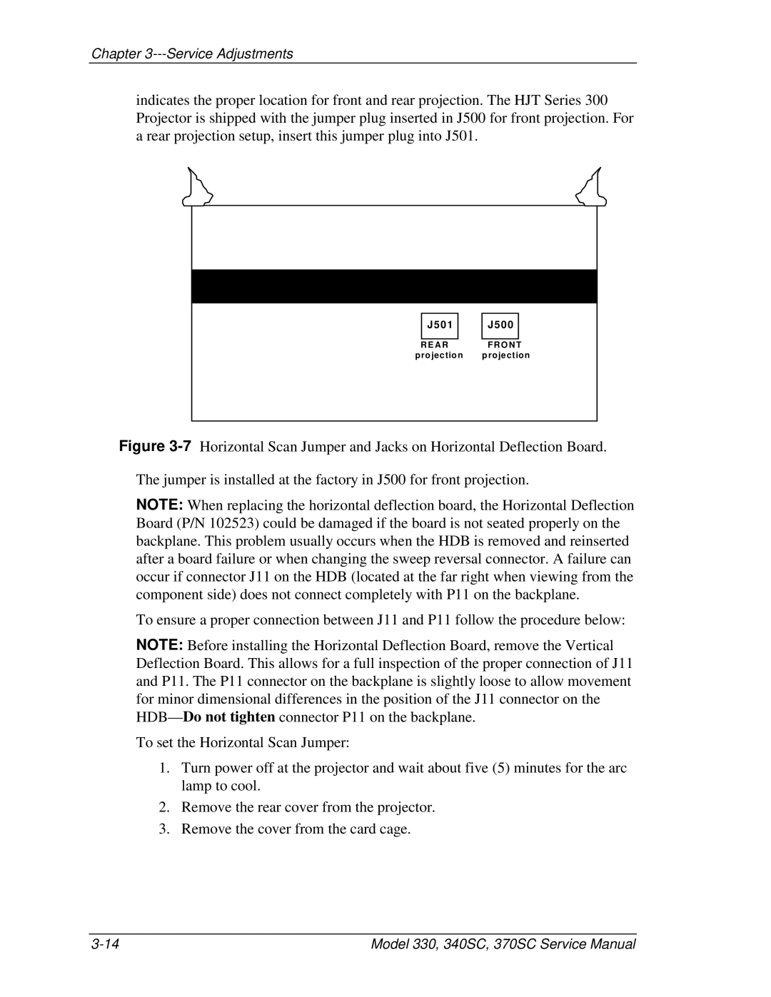
indicates the proper location for front and rear projection. The HJT Series 300 Projector is shipped with the jumper plug inserted in J500 for front projection. For a rear projection setup, insert this jumper plug into J501.
J 5 0 1
R E A R
p ro jectio n
J 5 0 0
F R O N T p ro jectio n
Figure 3-7 Horizontal Scan Jumper and Jacks on Horizontal Deflection Board.
The jumper is installed at the factory in J500 for front projection.
NOTE: When replacing the horizontal deflection board, the Horizontal Deflection Board (P/N 102523) could be damaged if the board is not seated properly on the backplane. This problem usually occurs when the HDB is removed and reinserted after a board failure or when changing the sweep reversal connector. A failure can occur if connector J11 on the HDB (located at the far right when viewing from the component side) does not connect completely with P11 on the backplane.
To ensure a proper connection between J11 and P11 follow the procedure below:
NOTE: Before installing the Horizontal Deflection Board, remove the Vertical Deflection Board. This allows for a full inspection of the proper connection of J11 and P11. The P11 connector on the backplane is slightly loose to allow movement for minor dimensional differences in the position of the J11 connector on the
To set the Horizontal Scan Jumper:
1.Turn power off at the projector and wait about five (5) minutes for the arc lamp to cool.
2.Remove the rear cover from the projector.
3.Remove the cover from the card cage.
Model 330, 340SC, 370SC Service Manual |
