Chapter 2—Functional Descriptions
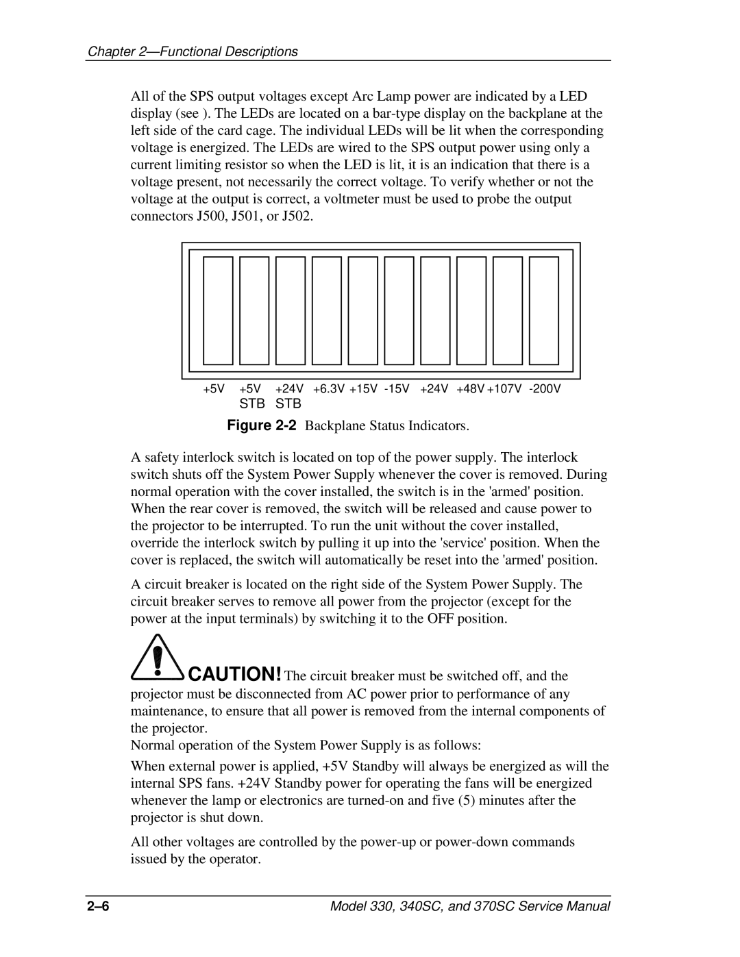
All of the SPS output voltages except Arc Lamp power are indicated by a LED display (see ). The LEDs are located on a
+5V +5V +24V +6.3V +15V
STB STB
Figure 2-2 Backplane Status Indicators.
A safety interlock switch is located on top of the power supply. The interlock switch shuts off the System Power Supply whenever the cover is removed. During normal operation with the cover installed, the switch is in the 'armed' position. When the rear cover is removed, the switch will be released and cause power to the projector to be interrupted. To run the unit without the cover installed, override the interlock switch by pulling it up into the 'service' position. When the cover is replaced, the switch will automatically be reset into the 'armed' position.
A circuit breaker is located on the right side of the System Power Supply. The circuit breaker serves to remove all power from the projector (except for the power at the input terminals) by switching it to the OFF position.

![]() CAUTION! The circuit breaker must be switched off, and the projector must be disconnected from AC power prior to performance of any maintenance, to ensure that all power is removed from the internal components of the projector.
CAUTION! The circuit breaker must be switched off, and the projector must be disconnected from AC power prior to performance of any maintenance, to ensure that all power is removed from the internal components of the projector.
Normal operation of the System Power Supply is as follows:
When external power is applied, +5V Standby will always be energized as will the internal SPS fans. +24V Standby power for operating the fans will be energized whenever the lamp or electronics are turned-on and five (5) minutes after the projector is shut down.
All other voltages are controlled by the power-up or power-down commands issued by the operator.
Model 330, 340SC, and 370SC Service Manual |