Chapter 2—Functional Descriptions
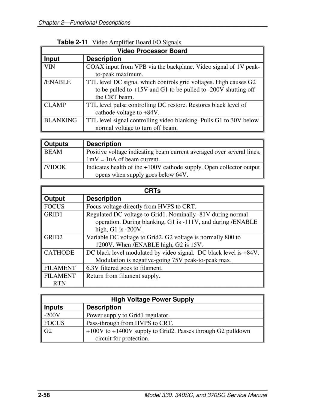
Table
| Video Processor Board |
Input | Description |
VIN | COAX input from VPB via the backplane. Video signal of 1V peak- |
| |
/ENABLE | TTL level DC signal which controls grid voltages. High causes G2 |
| to be pulled to +15V and G1 to be pulled to |
| the CRT beam. |
CLAMP | TTL level pulse controlling DC restore. Restores black level of |
| cathode voltage to +84V. |
BLANKING | TTL level signal controlling video blanking. Pulls G1 to 30V below |
| normal voltage to turn off beam. |
|
|
Outputs | Description |
BEAM | Positive voltage indicating beam current averaged over several lines. |
| 1mV = 1uA of beam current. |
/VIDOK | Indicates health of the +100V cathode supply. Open collector output |
| opens when supply goes below 64V. |
|
|
| CRTs |
Output | Description |
FOCUS | Focus voltage directly from HVPS to CRT. |
GRID1 | Regulated DC voltage to Grid1. Nominally |
| operation. During blanking, G1 is |
| high, G1 is |
GRID2 | Variable DC voltage to Grid2. G2 voltage is normally 800 to |
| 1200V. When /ENABLE high, G2 is 15V. |
CATHODE | DC black level modulated by video signal. DC black level is +84V. |
| Modulation is |
FILAMENT | 6.3V filtered goes to filament. |
FILAMENT | Return from filament supply. |
RTN |
|
|
|
| High Voltage Power Supply |
Inputs | Description |
Power supply to Grid1 regulator. | |
FOCUS | |
G2 | +100V to +1400V supply to Grid2. Passes through G2 pulldown |
| circuit for protection. |
|
|
Model 330. 340SC, and 370SC Service Manual |