3Remove the old fuses from the holder and replace with new fuses.
If the Controller still does not power on after replacing the fuse, contact Agilent.
Consult Table 4 for the appropriate replacement fuse.
Table 4 Fuses for 100 V, 120 V and 230 V Versions of 355 SCD and 255 NCD
| 100/120 V | 230 V |
|
|
|
Detector Back Panel |
|
|
|
|
|
Main AC Power | 15 A/250 V | T10 A/250 V |
| 3AG | 5 x 20mm |
|
|
|
Detector |
|
|
|
|
|
Electronics Power Supply (F1) | 250 mA/250 V | T125 mA/250 V |
| 3AG | 5 x 20mm |
|
|
|
Pump (F2) | 15 A/250 V | T5 A/250 V |
| 3AG | 5 x 20mm |
|
|
|
Ozone Generator (F3) | 1 A/250 V | T100 mA/250 V |
| 3AG | 5 x 20mm |
|
|
|
Photomultiplier Tube Cooler | 1 A/250V | T500 mA/250V |
| 3AG | 5 x 20mm |
|
| |
Dual Plasma Controller Back Panel |
| |
|
|
|
Main AC Power (2 fuses) | T2 A/250 V | 1 A/250 V |
| 5 x 20mm | 5 x 20mm |
|
|
|
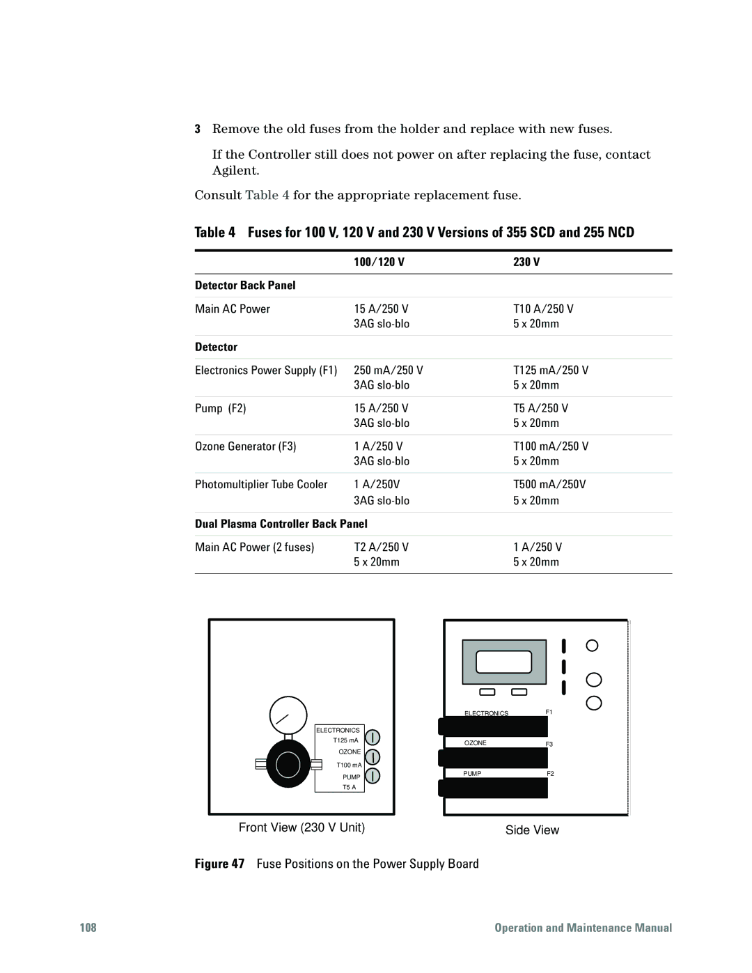
ELECTRONICS
T125 mA
OZONE
T100 mA
PUMP
T5 A
Front View (230 V Unit)
ELECTRONICS | F1 |
OZONE | F3 |
PUMP | F2 |
Side View
Figure 47 Fuse Positions on the Power Supply Board
108 | Operation and Maintenance Manual |