Step 9: Install Column Connections
The Burner operates under reduced pressure and there will be a slight vacuum on the end of the column. If a higher outlet pressure for the column outlet is desired, fused silica capillary restrictors may be attached to the end of the analytical column (both capillary and packed) prior to making the Detector connection.
Capillary Columns
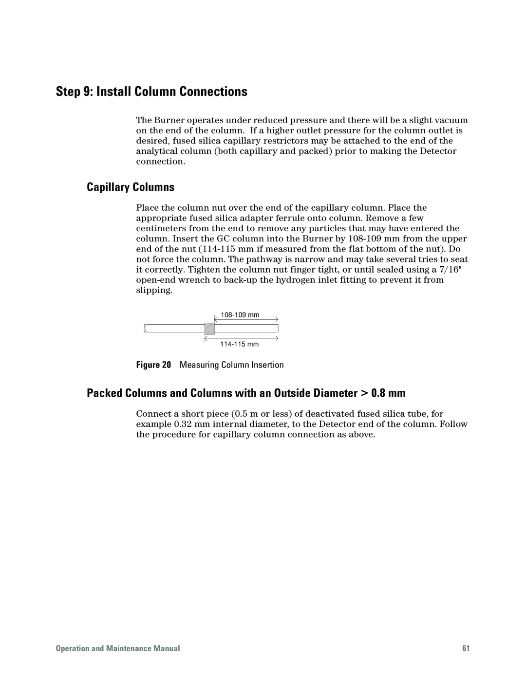
Place the column nut over the end of the capillary column. Place the appropriate fused silica adapter ferrule onto column. Remove a few centimeters from the end to remove any particles that may have entered the column. Insert the GC column into the Burner by
Figure 20 Measuring Column Insertion
Packed Columns and Columns with an Outside Diameter > 0.8 mm
Connect a short piece (0.5 m or less) of deactivated fused silica tube, for example 0.32 mm internal diameter, to the Detector end of the column. Follow the procedure for capillary column connection as above.
Operation and Maintenance Manual | 61 |