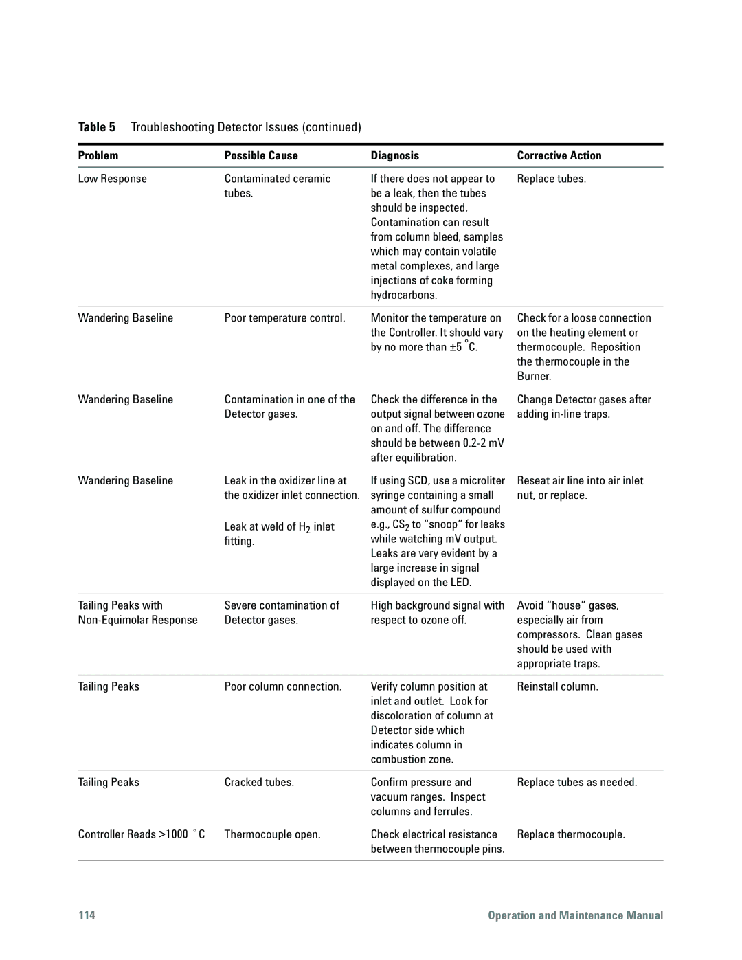
Table 5 Troubleshooting Detector Issues (continued)
Problem | Possible Cause | Diagnosis | Corrective Action |
|
|
|
|
Low Response | Contaminated ceramic | If there does not appear to | Replace tubes. |
| tubes. | be a leak, then the tubes |
|
|
| should be inspected. |
|
|
| Contamination can result |
|
|
| from column bleed, samples |
|
|
| which may contain volatile |
|
|
| metal complexes, and large |
|
|
| injections of coke forming |
|
|
| hydrocarbons. |
|
Wandering Baseline | Poor temperature control. | Monitor the temperature on |
|
| the Controller. It should vary |
|
| by no more than ±5 °C. |
Check for a loose connection on the heating element or thermocouple. Reposition the thermocouple in the Burner.
Wandering Baseline | Contamination in one of the |
| Detector gases. |
Check the difference in the | Change Detector gases after |
output signal between ozone | adding |
on and off. The difference |
|
should be between |
|
after equilibration. |
|
Wandering Baseline | Leak in the oxidizer line at |
| the oxidizer inlet connection. |
| Leak at weld of H2 inlet |
| fitting. |
If using SCD, use a microliter syringe containing a small amount of sulfur compound e.g., CS2 to “snoop” for leaks while watching mV output. Leaks are very evident by a large increase in signal displayed on the LED.
Reseat air line into air inlet nut, or replace.
Tailing Peaks with | Severe contamination of | High background signal with | Avoid “house” gases, |
Detector gases. | respect to ozone off. | especially air from | |
|
|
| compressors. Clean gases |
|
|
| should be used with |
|
|
| appropriate traps. |
|
|
|
|
Tailing Peaks | Poor column connection. | Verify column position at | Reinstall column. |
|
| inlet and outlet. Look for |
|
|
| discoloration of column at |
|
|
| Detector side which |
|
|
| indicates column in |
|
|
| combustion zone. |
|
|
|
|
|
Tailing Peaks | Cracked tubes. | Confirm pressure and | Replace tubes as needed. |
|
| vacuum ranges. Inspect |
|
|
| columns and ferrules. |
|
|
|
|
|
Controller Reads >1000 °C | Thermocouple open. | Check electrical resistance | Replace thermocouple. |
|
| between thermocouple pins. |
|
|
|
|
|
114 | Operation and Maintenance Manual |
