10Using a 5/8" wrench on the heater swivel nut and a 1/2" wrench on one of the flats of the tapered union fitting, tighten the heater swivel nut
adapter, rotate this fitting so that the brazed H2 line is aligned 180 ° (opposite) from the oxidizer Inlet port.
11Making sure that the Burner inlet fitting does not loosen, use a 1/2" wrench on a flat of the tapered union fitting and 9/16" wrench on the 1/4" Swagelok nut of the Burner adapter to tighten the tapered union fitting 1/4" past
12Rotate the quartz heater assembly so that the thermocouple and heater leads are in the same plane and pointed in the same direction as the peg on
the Burner inlet fitting. Turn the splitter fitting so that H2 inlet port is also aligned with the peg on the Burner inlet fitting.
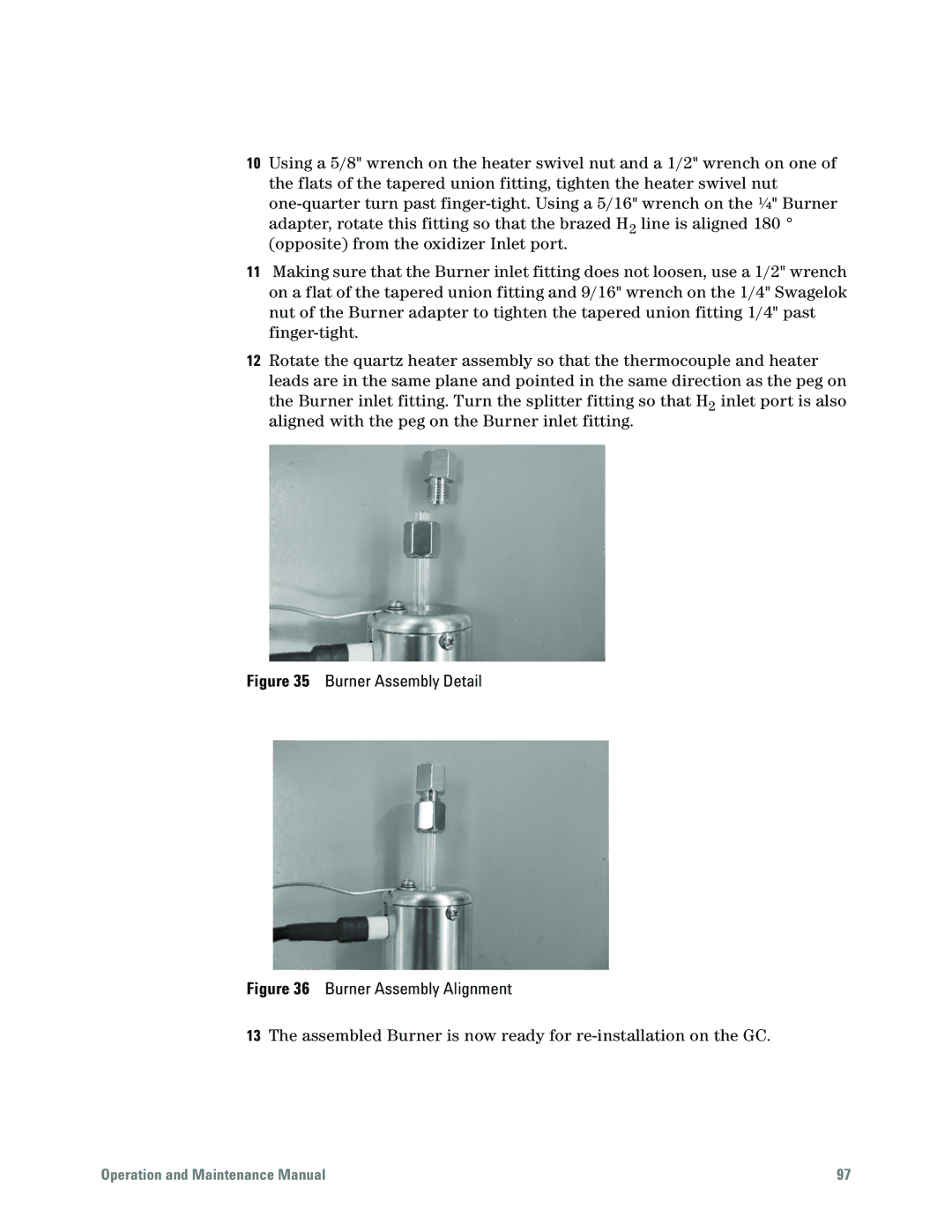
Figure 35 Burner Assembly Detail
Figure 36 Burner Assembly Alignment
13The assembled Burner is now ready for
Operation and Maintenance Manual | 97 |