Chapter 2—Functional Descriptions
The card cage is hinged in the rear to allow it to be folded backward for access to the CRT housing (when folding the card cage backward be sure that nothing is plugged into the rear electronic jacks or the plugs could be severely damaged). During normal operation, the card cage should be in its upright position to ensure proper cooling of the CRT enclosure.
A holddown screw is provided to secure the card cage and prevent it from rotating backward during shipping or when the projector is mounted in an upward- pointing position. The holddown screw is located on the lower, front, right corner of the card cage.
The rear panel of the card cage provides mounting for the projector controls. The VPB, which receives all image and sync inputs, is secured to the rear panel by four screws. The
2.6 Circuit Boards
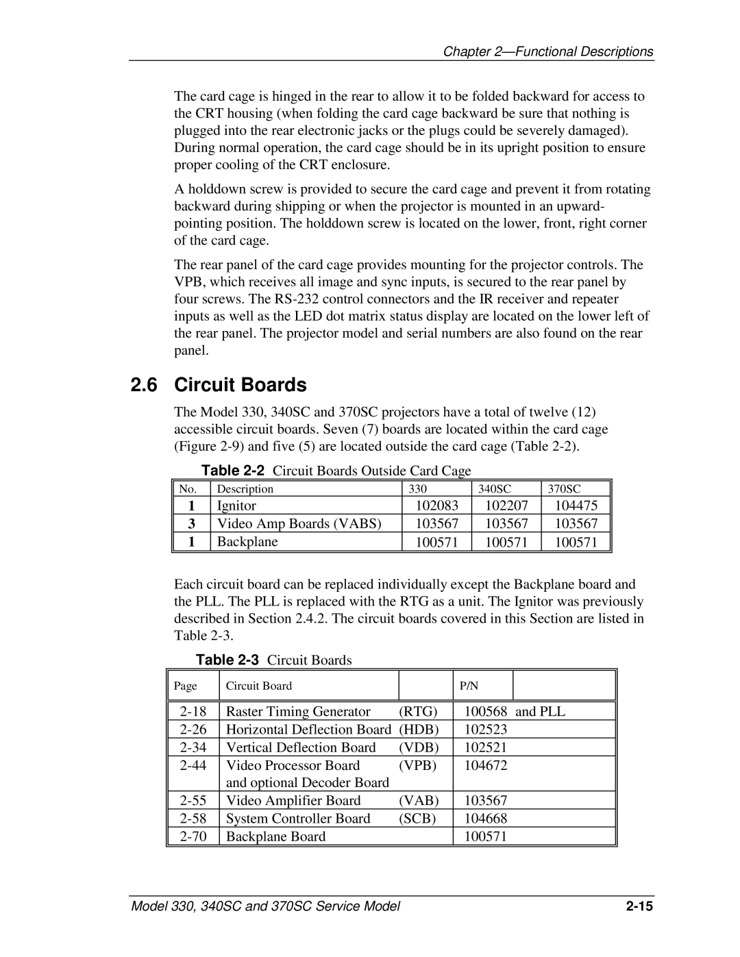
The Model 330, 340SC and 370SC projectors have a total of twelve (12) accessible circuit boards. Seven (7) boards are located within the card cage (Figure
Table
No. | Description | 330 | 340SC | 370SC |
1 | Ignitor | 102083 | 102207 | 104475 |
3 | Video Amp Boards (VABS) | 103567 | 103567 | 103567 |
1 | Backplane | 100571 | 100571 | 100571 |
|
|
|
|
|
Each circuit board can be replaced individually except the Backplane board and the PLL. The PLL is replaced with the RTG as a unit. The Ignitor was previously described in Section 2.4.2. The circuit boards covered in this Section are listed in Table
Table
Page | Circuit Board |
| P/N |
|
|
|
|
|
|
|
|
|
|
|
Raster Timing Generator | (RTG) | 100568 | and PLL | |
Horizontal Deflection Board | (HDB) | 102523 |
| |
Vertical Deflection Board | (VDB) | 102521 |
| |
Video Processor Board | (VPB) | 104672 |
| |
| and optional Decoder Board |
|
|
|
Video Amplifier Board | (VAB) | 103567 |
| |
System Controller Board | (SCB) | 104668 |
| |
Backplane Board |
| 100571 |
| |
|
|
|
|
|
Model 330, 340SC and 370SC Service Model |