Chapter 3---Service Adjustments
the mechanical CRT focus should not be adjusted. If the image is not sharp enough, proceed with the CRT mechanical focus adjustment below.
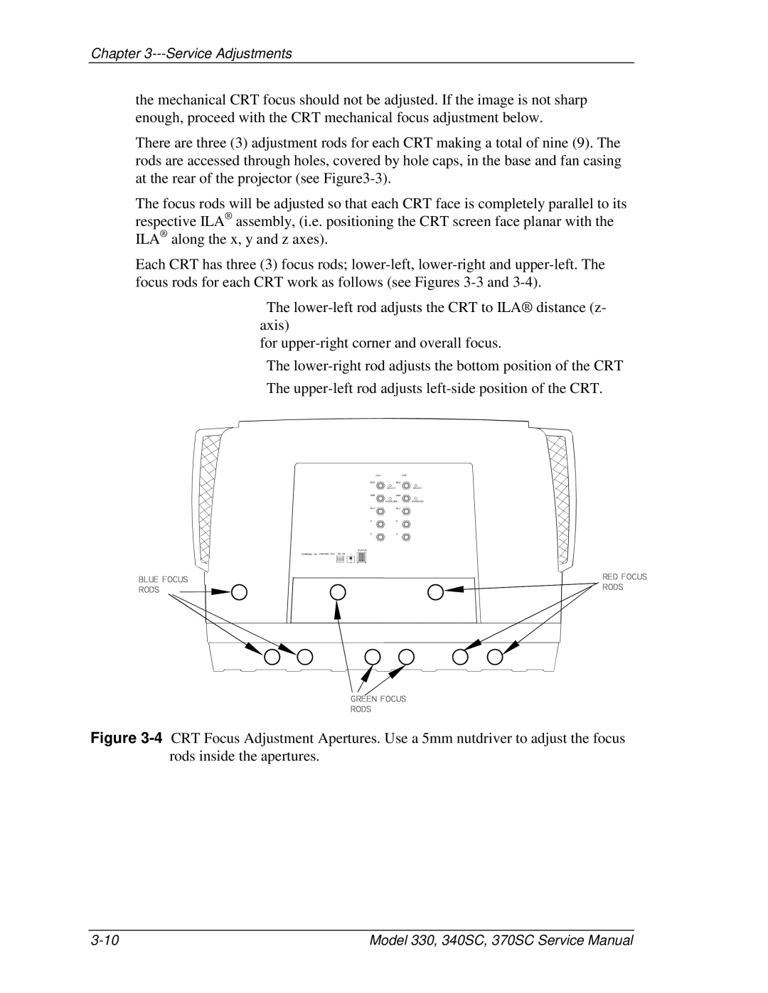
There are three (3) adjustment rods for each CRT making a total of nine (9). The rods are accessed through holes, covered by hole caps, in the base and fan casing at the rear of the projector (see
The focus rods will be adjusted so that each CRT face is completely parallel to its respective ILA® assembly, (i.e. positioning the CRT screen face planar with the ILA® along the x, y and z axes).
Each CRT has three (3) focus rods;
The
for
The
The
Figure 3-4 CRT Focus Adjustment Apertures. Use a 5mm nutdriver to adjust the focus rods inside the apertures.
Model 330, 340SC, 370SC Service Manual |
