Chapter 2—Functional Description
Circuit failure detection.
Beam current sense.
Arc protection.
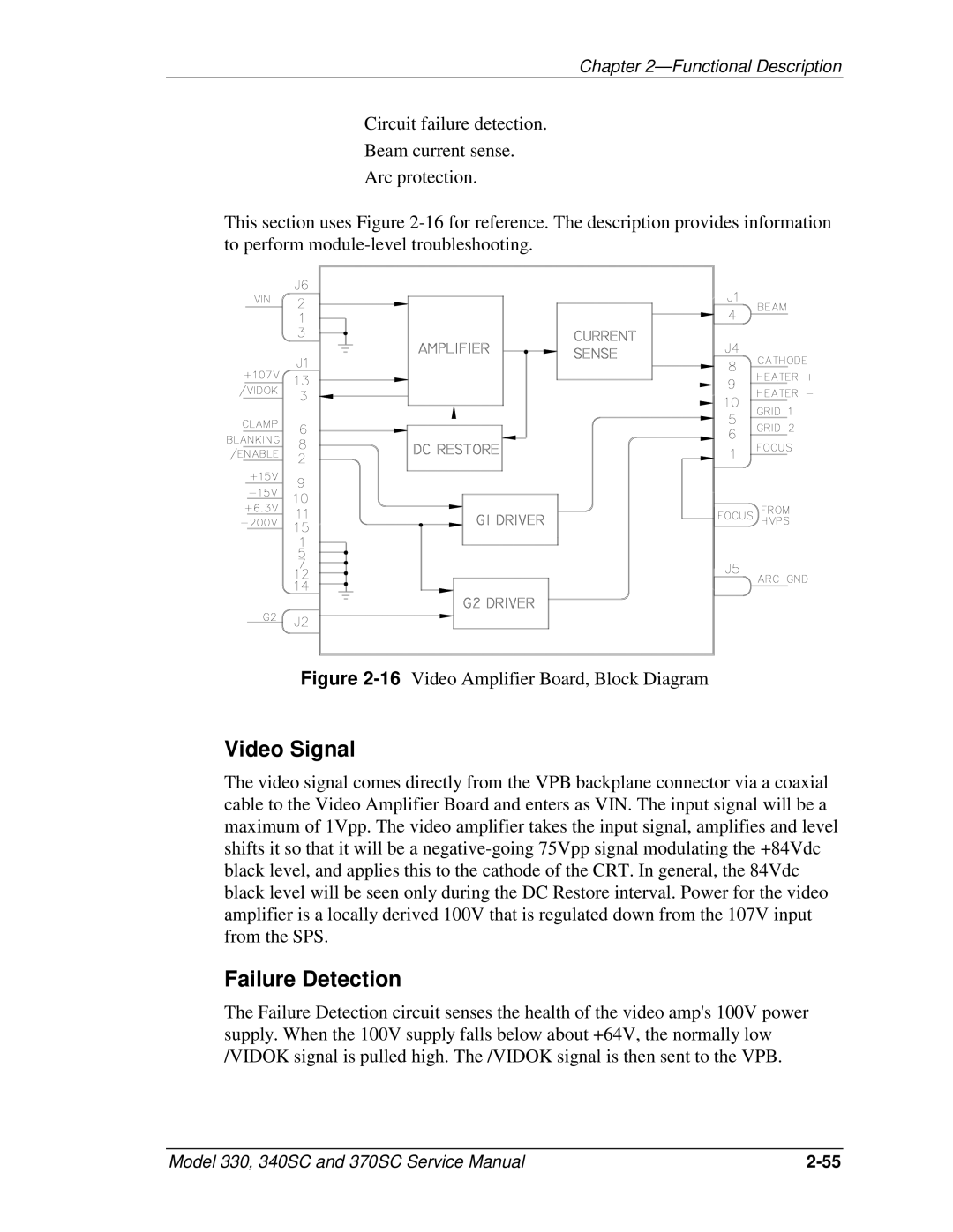
This section uses Figure
Figure 2-16 Video Amplifier Board, Block Diagram
Video Signal
The video signal comes directly from the VPB backplane connector via a coaxial cable to the Video Amplifier Board and enters as VIN. The input signal will be a maximum of 1Vpp. The video amplifier takes the input signal, amplifies and level shifts it so that it will be a
Failure Detection
The Failure Detection circuit senses the health of the video amp's 100V power supply. When the 100V supply falls below about +64V, the normally low /VIDOK signal is pulled high. The /VIDOK signal is then sent to the VPB.
Model 330, 340SC and 370SC Service Manual |