AI232 Port High Speed Asynchronous Line Card User’s Guide
Page
About this Document
Document Conventions
Laser Danger
Tip
Ground Caution Proper Cooling Caution
Electrostatic Discharge Caution
FCC Warning
Phone Support
Customer Assistance
Web Site Support
Email Support
Table of Contents
System Configuration
Link Configuration
TID Multiplexing
Diagnostics for TID Multiplexing
TOC-5
Appendix a AI232 Crash Codes
AI232 Commands AI232 Menu Aliases FTP Sessions
Product Description
Features
System Diagnostics
Standalone Configuration
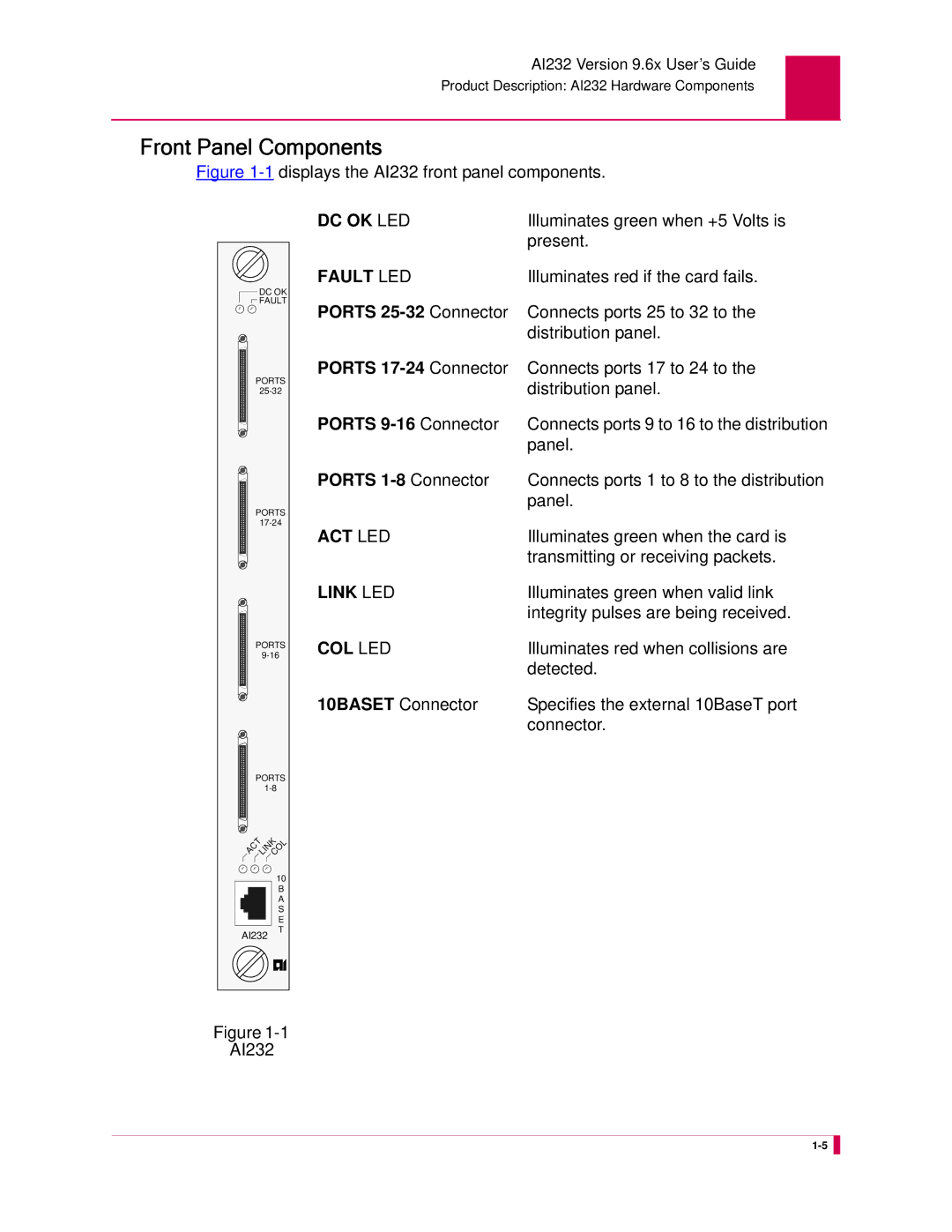
AI232 Hardware Components
Ports 1-8 Connector
Ports 25-32 Connector
Ports 17-24 Connector
Ports 9-16 Connector
Component Description
Technical Specifications
Model DP232-19/23
Specifications for DP232-19/23
Description Specification
Distribution Panels
DCD
Pin Assignments Signal
Ports Places
Installation Procedure
Model DP232-RJ45
Connect to the AI232
Pin Signal
Specifications for DP232-RJ45
Parts List
Install the mounting flanges in the desired location
Description Quantity
Cable CAB467 Places DP232-RJ45
Asynchronous to TCP/IP Application
Typical Applications
Illustrates a modem multiplexer application
Modem Multiplexer Application
Using the AI198 Menu System
Accessing the Menu System
Submenus
Navigating the Menu System
Menu Numbering Structure
Types of Menu Items
Data
Toggles
Menu re-appears with the entered IP address
Menu Item Descriptions
Functions
Menu Item Description
Exiting the Menu System
AI232 Local Menu System
Identifying AI232 Menu System Security Options
Multilevel User Name and Password Security
Radius Authentication
TACACS+ Authentication
PPP Authentication Protocols PAP and Chap
Logging Into AI232
Using a Telnet Connection for Login
Consecutive failed login attempts
Using an Asynchronous Port for Login
Number of consecutive failed login attempts
Accessing the Local Menu System
Direction Keys
Navigating the Local Menu System
Identifying Types of Menu Items
Data Entry Items
Toggle Items
Send
Accessing the Help Menu
Save the changes
Exiting the Local Menu System
AI232 Version 9.6x User’s Guide
System Configuration
Format
General System Properties Configuration
Destination Menu Break Sequence
Description
Menu Item Type
Configuration in the AI198 Menu System
Configuration in the AI232 Local Menu System
Ethernet Port Settings
Toggle for both menu items
This menu item sets the FTP server port number
FTP Port
This example displays 16 FTP port number set to
IP Settings
Menu Item Types
System Prompt
Access the System Menu
This item sets the system prompt value in the CLI
Toggle
TCP Settings
To on
This item sets the Telnet port value for AI232
Telnet Port
This example displays Telnet Port set to
Server Settings
Radius Configuration
Enabled
FALLBACK. The default is Disabled
To configure the shell/FTP Radius option Access Menu
Shell/FTP Options
Enabled
TACACS+ Configuration
Shell/FTP Options
00049
Authentication Traps
Snmp Configuration
AI232 Local Menu Item Configuration
Data for all menu items
Community Names
WriteComm Menu
Following example displays
Node Information
Contact Persons
Snmp Manager
10.65.32.4
IP Address Settings
Static Route Configuration
Inactivity Timeout
TID to Modem Mux Configuration
Following are available
Initialization String
This example displays Inactivity Timeout set to
This example displays Init String set to conn23
Port Bit Settings
Toggle for all menu items
TID to Route
AI232 Local Menu Item Configuration
Daylight Savings Time
Time Configuration
Settings
Sntp Settings
Access the Time Menu located under the System Menu
This following example displays
Time Zone
AI232 Version 9.6x User’s Guide
Link Configuration
Asynchronous PPP
AI232 has 3 configurable link types
AI232 Link Types
Asynchronous
Modem Multiplexer
Link Type Availability
Connect Options Configuration
Access Menu For 02 Alias, enter 2, and the alias name
Alias
This example displays 02 Alias set to async.4.1
Call Retry Interval
This example displays 03 Call retry interval set to
Connect String
00134
Is on
Connection Settings
Connection settings are configured using three menu items
Default is OFF
00030
Link Application
Login
Disconnect Inactivity Timer Settings
Disconnect Options Configuration
Disconnect inactivity timer when the link receives a call
Off. The default is On This example displays
Select on or OFF. The default is on This example displays
Is Off
Disconnect settings are configured using two menu items
Disconnect Settings
Default is on
Disconnect String
Disconnect
Auto Disable Error Limit
General Link Properties Configuration
Async, AsyncPPP, and ModMux
Flow Control
This menu item defines a description for a link
Access the Link Menu
Link Description
This example displays SW Flow Control set to XonXoff
Link Number
Link State
This menu item enables or disables a link
This example displays 01 Link number set to
Link Type
This example displays Link state set to Disabled
Async and AsyncPPP
Port Data Bits
This example displays Port data bits set to Seven
Port Parity
Data in the AI232 local menu system
Port Speed
This example displays Port parity set to Odd
This menu item defines the baud rate for a port
Menu 4.2.14.12.5 appears
Port Stop Bits
Xon Repeat Interval
This example displays 10 Xon Repeat interval set to
AsyncPPP and ModMux
General PPP Properties Configuration
Ipcp Address Settings
Following menu items are available for PPP configuration
Ipcp Address Parameters
Set to
Maximum Unit Settings
For an Ipcp network control protocol
Network Control Protocol
Ipcp
Modem String
Modem Option Configuration
Dialing Time-out Interval
This example displays Dialing time-outset to
Number of Dial Attempts
This example displays Number of dial attempts set to
Modem Setup Menu
Local Authentication Settings
PPP Authentication Configuration
PAP
RAS Option
This example displays RAS Option set to RADIUS/Fallback
Remote Authentication Settings
Chap
DTR State Configuration
RTS/DTR Lead Control Configuration
RTS State Configuration
Flow Control
DTR connect state Off DTR disconnect state
TID Multiplexing
Overview
AI232 Version 9.6x User’s Guide
Configuring the Parent Alias
TID Multiplexing Configuration
Menu appears
Values are 1 to
Destination
TidforAI232 Defines the terminal identifier for AI232
Configuring the Children Aliases
During the parent alias configuration
TIDtid
For Alias name, enter
Example Configurations
Second child connection
YES
Alias Edit Menu Alias Name 172.16.30.61#6001
PARENT1.1
Alias Edit Menu Alias Name
Response Item Description
TID Multiplexing Troubleshooting
Parameters
Normal Response Format
Normal Response Example
Error Response Format
Error Response Example
Diagnostics for TID Multiplexing
Errcde
AI232 Version 9.6x User’s Guide
Alias and Call Routing Configuration
Upstream
Downstream
Incoming Outgoing Asynchronous TCP/IP CallCall
AI232 Card B IP address
AI232 Version 9.6x User’s Guide
Configuring an Alias in the AI198 Menu System
Configuring an Alias
Call Routing
AI232 Version 9.6x User’s Guide
AI232 Version 9.6x User’s Guide
Configuring an Alias in the AI232 Menu System
For Display Alias in Destination Menu, select Yes or No
Source/Destination Protocol Tables
Source
Source Destination Menu Item Information
Menu Item Information
Async break
TCP/IP Source Without Telnet Breaks AI198
TCP/IP Source With Telnet Breaks AI198
Async with
TCP/IP Source Without Telnet Breaks AI232
Asynchronous Source Without Breaks AI232
Asynchronous Source With Breaks AI232
Telnet break Example asy.3
TCP/IP Source With Telnet Breaks AI232
Module Types
Protocol Processing Modules
Return followed by a line feed
Specify up to 16 characters
To zero, this option is turned off
Characters. The packet module accepts only one -S parameter
Provides TL1 packetizing and prevents breaks from passing
Provides TL1 packetizing and sets the packetizing timer to
Seconds
Feed and delete
Echo and will SGA
Echo 1 when the connection is initiated. Initiates will SGA
Provides Telnet handling, but prevents breaks from being
Propagated upstream
Alias Macros
Start Symbols
Alias Macro Components
Variable Value
Comments
Constants
Variables
Operators
Wildcard Symbols
Operator Description
Alias Macro Function Description of Operation
Returns the length of string
Match any of the expressions, then default is
Greater than the length of string, the function
Returns the entire string
Configuration Examples
Alias Macro Configuration
=LA,PA,’#’,1-1=MYIP1
AI232 Version 9.6x User’s Guide
AI232 Commands
Establishing a Local Shell Connection
Commands Overview
Shell Commands
Shell Connections
Displaying winslc Command Logging
Winslc Commands
Establishing a Remote Shell Connection
Log/Alarm Message Header
Using winslc Commands
Header Element Description
Specifies the line card baseport number
Introduces the log/alarm message
Specifies the current date
Specifies the message severity level
Formats
Command Type
Command Defaults
Aaa account
Connections
Enables TACACS+ authentication
Disables TACACS+ authentication
Aaa authen
Priv-lvl
Aaa author
Aaa chpass
Aaa fallback
Enabled TACACS+ fallback
This example displays the disabling of TACACS+ fallback
Disabled all links
Disables TACACS+ authentication
Enables TACACS+ authentication with no fallback
Enables TACACS+ authentication with fallback
Specifies the name of an existing profile
No associations configured
Aaa profile
Profile. Individual values are separated by commas ,
Aaa profile 2 newprof1
Made. Valid values are 1 to
Aaa retry
Connection attempt
Display Item Description
Aaa stats
Where AI232’s system log was used for accounting
Displays the number of TACACS+ authorization
Displays the number of failed TACACS+ authorization
Authorization instead of the TACACS+ server
Aaa summary
Displays the TACACS+ accounting status of user login events
Displays the status of FTP access as AAA TACACS+
Displays the TACACS+ authorization method for the AI232
Per-command based on per-command request/reply handling
Values are 1 to
Aaa timeout
TACACS+ server when a connection attempt is made. Valid
Resets the timeout value to its default
Command Type shell Formats
Alarm
This example displays all system alarms in group links
This example displays all alarms by severity level
This example displays alarms for links 5-8in group links
This example displays the unmasking of alarm group links
Arp
Command Types
Column Description
172.16.30.117
Break
232break 10.40.5.11#1821 Breaking connection 10.40.5.11#1821
Example, 1,2-3 to reset error counters for links 1, 2,
Creset
To reset error counters for links 1, 2,
Reset error counters for links 1
Date
Debug
This example displays the enabling of all debug data logging
This example displays the deletion of file log.txt
This command deletes a specified file that resides on AI232
Delete
Filename Defines the name of the file to delete
Diag-conn
Logic 4 and Pattern 5 are considered
This option prompts for the ID of the connection to view
Displays details for that connection
Pattern 1, Logic 2, and Pattern 3 are evaluated before
Diag-eth
Using Interpretation Mode
Using the Help Option
Defines the source address MAC, IP, or TCP/UDP
Following formats apply to filters
Adds a filter
Deletes a filter
Protocol filters are
MAC/IP address settings
Defines the TCP/UDP port number regardless
Adds or deletes a specific protocol filter. Available
This example displays Ethernet diagnostic help information
Ijkl
FF FC
This example displays the deletion of all filters
This example displays the deletion of filter protocol tcp
Diag-info
Display
Last reset
Displays the name of the Streams resource
Displays the number of free or available Streams resources
Specifies that the link is not established
Connection to be enabled
Displays the link number
Displays the state of the driver. Two states are available
Displays the number of short received frames
Had CRC errors
Displays the number of frame length violations
Received packets
Displays the number of times transmitted frames
Displays the number of frames received on
Connection
Displays the number of bytes received on
Displays the number of bytes received on the connection
Does not indicate an error
Displays the number of transmit errors that have occurred
Displays the number of frames received on the connection
Error is recorded when the following events occur
Errors
Displays the number of alignment errors
Excessive deferral timer is exceeded. An excessive deferral
Ethernet interface is uninitialized
Ethernet interface needs to be reset
Displays the current state of the Ethernet interface.
Following values may appear
Option Function
Diag-line
Diag-line
Displayed as Ascii String
Only present in data packets, then the data byte count is
Baseport Defines the baseport number for AI232
Diag-tconn
This example displays all available files
Dir
This example displays an exit from the current shell session
Exit
Defines the name of the file to display
This command displays the first few lines of a file
Defines the number of lines to display. The default is
Head
This example displays help information for command show
This example displays a list of all available commands
Help
Formats Examples
This command displays the current user name and profile
This example displays the current user name and profile
This example displays the configured IP address information
Ip init
Enter IP Address Range default 1 Setting range to 232
Restarts the serial links
Enables the serial links
Disables the serial links
Link
This example displays the stopping of links 6
This example displays the starting of links 1 through 4
Log
This command turns the display of log messages on or off
Logout
This command closes a shell session
This example displays the closing of a shell session
This command displays a list of available files
Menu
This command accesses the AI232 main menu system
This example displays the AI232 Main Menu
Modmux
Displays the phone number that was dialed
232more log.txt
More
Baseport Defines the AI232 baseport number
This command forces AI232 to crash dump and halt
Panic
Winslc
Passwd
This command changes an existing user’s password
Ping
Pppstatus
IP address of AI232 if the link status is Running
Displays one of the following
Profile
Deletes commands from a user profile
Adds commands to a profile and optionally adds write
Defines the name of a command to associate with a user
Adds write permission for a command that otherwise would
This example displays PVC information for link
Pvclist
Column Description
This command resets AI232
Reset
This example displays the resetting of AI232
Router
Ipaddress Defines the IP address of the default router
Usage Notes
Extension
Configuration file
Specifies the option that deletes a configuration file
Selcnf
Sholog
PDisplays the content of the file one page at a time
Show
Displays the date and time
Displays the default and backup gateway IP address
Displays the IP address, subnet mask, and high IP address
Displays the version number of AI232
Staeia
This command displays the status of the EIA leads
Lead is negated
DCD
Standalone
This example displays the current standalone mode status
Staslc
Displays the number of overrun errors
Is asserted and means the signal is negated
Displays the number of parity errors
Displays the number of framing errors
Syncflash
Tacacs info
Tacacs server
0.0
Tacacs server ip
Specifies a server number or range of server numbers. Valid
Defines the server IP address
Tacacs server phase
Tacacs server phase 1-5,8 disable account
TCP port
Tacacs server port
Defines the TCP port number for the TACACS+ servers. Valid
Values are 1 through
Tacacs server secret
No secret configured
Tacacs server summary
Associated servers are enabled + or disabled
Displays the server numbers. The +/ signs indicate if
Displays the TACACS+ shared secrets passwords for specified
This example displays a TACACS+ debug log file
Tacacs sholog
Tacacs stats
Server that had a sequence number that was out of order
Displays the number of errors that occurred when AI232
When AI232 attempted to read a packet from the TACACS+
Were received when AI232 attempted to read them from
This example displays the last 20 lines of file log.txt
This command displays the last few lines of a file
Tail
Specifies that a line number value will be entered
Tcpoutconn
Default is
This example changes the telnet port to port
Telnet
Defines the IP address of the Tftp server to which the file
Tftp
Downloads a file from the Tftp server
Uploads a file to the Tftp server
Special characters
Defines the name of the source file after it has been
File name is specified, the file will have the same name as
Source file
Tftpboot
113
Timezone
115
Type
Defines the file for which you want to view the contents
Displays text from the file one page at a time
Defines the source file to copy
Update
Uptime
Profilename Permission
Useradd
Permission is assigned
Specifies a user who can login into AI232 and access
Retrieve status or to change the configuration
Destination at login. The destination is specified when
Userdel
Users
Who
Is 1 to 120 seconds
Xon-interval
This appendix provides information about AI232 crash codes
AI232 Crash Codes
Crash Codes
Error Code Description Hexadecimal Decimal
Common Crash Codes
AI232 Crash Codes
System Failure Crash Reports
Kentrox Technical Support
AI232 Version 9.6x User’s Guide
Standalone Mode and Switch Mode
Transfer the software image to AI232
Standalone Mode
Downloading Software for a Standalone AI232
At the FTP prompt, open AI232
Configuring BOOTP/TFTP
Transfer the software image to AI198
Switch Mode
Downloading Software for AI232 in Switch Mode
At the FTP prompt, open AI198
Winslc baseport update
AI232 Version 9.6x User’s Guide
Commands for AI232 TACACS+ Server Enhancements
Following keyword lets users access destinations
AI232 Commands
Menu Menulink
AI232 Menu Aliases
Provides FTP read access
Following AI232 keywords apply to FTP access
FTP Sessions
Acronym Meaning
Border Gateway Protocol
Command and Control Interface
Challenge-Handshake Authentication Protocol
Command Line Interface
Digital Service Unit
Channel Service Unit
Dynamic Host Configuration Protocol
Domain Name Service
End System to Intermediate System
File Transfer, Access, and Management
End System
Electrostatic Discharge
Link State Update
Integrated Services Digital Network
Internet Service Provider
Link Access Protocol Balanced
Multimode Fiber Optic Cable
Nonservice Affecting
Network Service Access Point
Operations, Administration, Maintenance, and Provisioning
QoS Quality of Service
Password Authentication Protocol
Private ID or password
Plain Old Telephone Service
Switching Center Control System
Remote Network Monitoring Specification
Serial Alarm Module
Service Advertisement Protocol
Time Division Multiple Access
Switched Virtual Connection
Terminal Access Controller Access System
TID Address Resolution Protocol
Virtual Channel
XML Key Management Specification
Xerox Network Services
Unshielded Twisted Pair