MASTER-K 120S series
Safety Instructions
Design Precautions
Poor connection could cause an input or output failure
Not doing so could cause a malfunction, failure or drop
Such debris could cause fire, damage, or erroneous operation
Not doing so could result in erroneous operation
Not doing so could cause poisonous pollution or explosion
Doing so could cause electric shock or erroneous operation
Not doing so can cause a malfunction
Revision History
Contents
Communication I/F Module ················· 4
Power Supply / CPU
104
Input and Output Modules
Usage of Various Functions
100
Communication Function
Installation and Wiring
Troubleshooting
Maintenance
Guide to Use This Manual
General
Features
RTC
Terminology
Kglwin
FAM
Output Contact
G7L-CUEB, G7L-CUEC
Overall Configuration
Basic system
Expansion
MASTER-K120SMASTER-K120S
System Configuration Cnet I/F system
Communications system
MASTER-K120S
G7L-CUEC
1n Communications system
MASTER-K120S G7L-CUEB
RS-232C ⇔ RS-422 Converter
CPU
Product Functional Model
Product Functional Block
Main Unit
Main Unit Economic type
Main Unit Standard type
Expansion Modules
General Specifications
General Specifications
LED
Main Unit
PWR LED
RUN LED
Name Description
1 60-points main unit Standard
2 40-points main unit Standard
3 30-points main unit Standard
4 20-points main unit Standard
5 30-points main unit Economic
8 10-points main unit Economic
Names of Parts 6 20-points main unit Economic
7 14-points main unit Economic
2 10points I/O Module
Expansion I/O Module
1 20points I/O Module
Names of Parts 3 8points I/O Module
1 A/D·D/A Combination Module
Special Module
G7F-DA2I
Names of Parts 2 D/A Conversion Module
RTD Input Module
Names of Parts Analog timer Module
Fnet I/F Module
Communication I/F Module
Cnet I/F Module
DeviceNet I/F Module
Option Module
Names of Parts Pnet I/F Module
DR/DRT/DT60U
Power Supply Specifications
Standard Type
Economic Type
RUN, STOP, PAUSE, Debug
CPU Specifications
Items Specifications Remarks
D0000 ~ D4999 Data register Operation modes
JOG
Items Specifications
RUN, STOP, Pause
Power Supply / CPU Economic Type
K7M-DR10UE K7M-DR14UE K7M-DR20UE K7M-DR30UE
User defined protocol support RS-485 1 port
Remarks Dedicated protocol support
Modbus protocol support RS-232C 1port Cnet I/F Function
Cyclic operation
Operation Processing
Operation Processing Method
Interrupt operation method
Operation Processing at Momentary Power Failure Occurrence
Momentary power failure within 10 ms
Momentary power failure exceeding 10 ms
Expression for scan time
Power Supply / CPU Scan Time
Scan Watchdog Timer
Setting range of watchdog 10 ~ 6,000msunit 10ms
Off delay timer
Power Supply / CPU Timer Processing
On delay timer
Monostable timer
Integral timer
Retriggerable timer
Up-down counter
Power Supply / CPU Counter Processing
Up counter CTU
Down counter CTD
T1 + T2
Ring counter
Maximum counting speed
OFF
Classifications of Program
Program Execution Procedure
Program
Usage of interrupt program
Interrupt Programs
Scan program
Interrupt program
HSC driven interrupt
Parameter setting Time driven interrupt
Process driven interrupt
Operation mode at error occurrence
Error Handling
Error Classification
Power Supply / CPU
Operation Modes
RUN Mode
Processing when the operation mode is changed
Operation processing contents
Debug modeStandard type only
Power Supply / CPU Stop mode
Pause mode
Processing when the operation mode changes
Operation method
Operation Mode Change
Operation mode change methods
Debug operation conditions
Mode change Remote operation
Self-diagnosis
Functions
Forced I/O setting method
Power Supply / CPU 2 I/O Force On/Off function
Power Supply / CPU
Force on/ off Processing timing and method
Special data register for forced I/O
Clear error data
Power Supply / CPU Direct I/O Operation function
System error history
Special data register for error history
Memory Configuration
O No. allocation method
I/O Address Allocation
Usage
Built-in Cnet Selection Switch
ROM Mode
Structure
Power Supply / CPU
Saving the user’s program on the external memory module
Installation connector
External Memory Module
Run the PLC with a program of external memory module
Following message box will be displayed
RTC Module
Read RTC data
Read RTC data from Kglwin
Saturday
Write RTC data
Date expression
Number Date Sunday Monday Tuesday Wednesday Thursday
Opening/shutting of electric current
Input / Output Specifications
Input and Output Specification
Main unit
Digital Input Specification
Specification
Circuit diagram
DC24VDC24V
Input wiring
Voltage
Example of external devices
Current
PNP
It’s the same with the one for the main unit
Input and Output Specification Expansion Module
Specifications
Model Expansion Module Specification
K7M-DRT40U
Digital Output Specification
Main unit Relay Output
Internal Circuit Relay
Economic type Model Main Unit Specifications
Circuit
DC24V DC24V
Output wiring
DC5V DC24V
AC110/220V
P42,P43 Internal Circuit 24V
Model Main Unit Specifications
K7M-DRT/DT20U K7M-DRT/DT30U K7M-DRT/DT40U K7M-DRT/DT60U
P40,P41 24V Internal Circuit
DC12V/24V
AC110/220V DC5V/24V AC110/220V
It’s the same with the output circuit of the main unit
… …
Refer to 7.2 ‘Special Functions’ for the special modules
Model Expansion Module Specifications G7E-TR10A
DC12/24V
High-speed counter function
Performance Specifications
Input specification
Built-in Functions
Input Common Input common terminal
Names of wiring terminals
Input pulse Preset input
COM0
External interface circuit
Wiring instructions
Open collector output pulse generator
Wiring example
Pulse Generator
Voltage output pulse generator
Flag Instruction
InstructionHSCST
Hscast
High speed counter Available device
Parameter Setting
Usage of Various Functions
Usage of Various Functions
Usage of Various Functions
Usage of Various Functions
Usage of Various Functions
Programming example
Remark
Minimum input pulse width
Using method
Usage of Various Functions Pulse Catch Function
Usage
Remark
Usage of Various Functions Input Filter Function
Function
External input signal Scan program
Usage of Various Functions External Interrupt Function
Minimum processing time
For the details , refer to Kglwin manual
Manipulation Value
Introduction
Kp is too large
MV = KpTi Edt
System response when a long integration time given
MV = Kp ⋅ Td dEdt
Example of integral windup
Perform the PID operation
Perform the auto tuning operation
Where, h sampling period
PID8
Usage of Various Functions
ENP ENI END
Usage of Various Functions
DigitalOutput = Temp.⋅10 +
Tse +1
Flag
Instruction
PID8
PID Control Instruction Available device
PID8AT
PID Auto Tuning Available device
TPR
Program Example
KGL-WIN
Usage of Various Functions
Usage of Various Functions
Usage of Various Functions
Usage of Various Functions
Error code list
D4980
Voltage DC 0 ∼10V
Performance specification
Usage of Various Functions 1 A/D·D/A Combination module
G7F-ADHA G7F-ADHB
Voltage Input Current Input
Names of parts and functions
Explain about names of parts and functions G7F-ADHA
① RUN LED
Analog output terminal Voltage output Current output
G7F-ADHB
Right current input
Left voltage input
4000
Wiring
Analog input characteristics Voltage input
O converstion characteristics
Analog output characteristics Voltage output
Program example
Usage of Various Functions
Remark
Usage of Various Functions 2 A/D Conversion module
① RUN LED
Be sure to use two-core twisted shield wire
Analog/Digital conversion characteristics
Program example
Program
G7F-DA2I G7F-DA2V
Usage of Various Functions 3 D/A Conversion module
③ ①
Parameter setting
Scaling function
G7F-DA2I ~20mA output
Digital/Analog conversion characteristics
Program example
On normal operating
Usage of Various Functions Analog timer
Name Contents Indicate the operating status the G7F-AT2A
Off DC 5V power off or the G7F-AT2A module fault
Usage of Various Functions
Explain about names of parts and functions
Name Contents
CH1 CH0
Parameter setting Digital conversion value register
Error code D4880 ∼D4885
BD bC bB BA b9 b8 b7 b6 B5 b4 b3 b2 B1 b0 D4880
6000
Temperature conversion characteristics
Digital conversion value
4000 2000
Burn-out detection function
Type Wire
No wiring Shield wire
Wire resistance ≤10 Ω
Main unit input contact P000 ~ P023
RTD input module
P0000
P0040 ~ P004F
Positioning FunctionDRT/DT type only
Specification
Items Specification
Names of wiring terminal
Output SpecificationP40, P41
COM1
Internal circuit and wiring example
Positioning function
Parameter setting
Setting Incremental End Single 000 100
Usage of Various Functions Positioning function
Please refer to the ‘7.3.4 Instruction’ for details
Speed Control Uniform Speed Operation
Absolute End Single
Operation pattern
Operation methods are as follows Remark
Step No. can be assigned within 1 ~ Items of parameter
Absolute End Single 10,000 50,000 20,000 30,000 40,000
Operation Mode End Operation
Start command Posist
Example End operation Speed
Absolute Keep Single 10,000 50,000 20,000 End 30,000 40,000
Keep Operation
Absolute Continuous Single 10,000 50,000 End 20,000
Continuous Operation
Operation Method Repeat Operation
Positioning stop
Positioning start
Origin return method
Origin Detection when Approximate origin turns off
Return to OriginPOSORG Rising edge ↑
Origin Detection by approximate origin
This is the method using the approximate origin signal only
JOG Operation Posjog Level input
Speed Override CommandPOSSOR Rising edge ↑
Point
External Input Stroke High/Low Limit
Error and Output Prohibition
Positioning parameter
Speed Limit
Backlash Compensation Amount
Bias Speed
DOG
Origin return parameter
② Origin return-Low speed
Dwell Time
Positioning parameter
Operation Mode is divided into following three kinds
Usage of Various Functions
Positioning Indirect Start Instruction Available device
Usage of Various Functions Instructions
Positioning Indirect startPOSIST
Posist
Positioning Indirect Start Available device Instruction
JOG OperationPOSJOG
Control instruction designation
Positioning Control InstructionPOSCTR
Posctr
Posprs
Current position preset Posprs
Current position preset Instruction Available device
Preset value designation
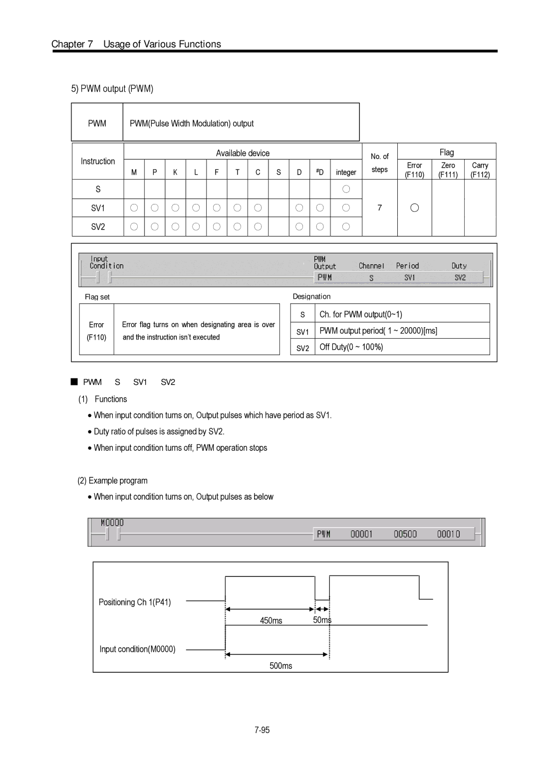
SV1 SV2
PWM output PWM
PWM
Speed control operation Instruction Available device
Speed control operation Posvel
Posvel
Ch. for speed override0~1 SV Speed 5 ~ 100,000pps
Speed override Possor
Possor
Speed override instruction Instruction Available device
Posdst
Positioning direct startPOSDST
Return to origin Instruction Available device
Return to originPOSORG
Posorg
Device Function Description
Usage of Various Functions Flag list and Error codes
Flag list
101
Corrective action Code
Error code
Error Condition
H48
103
Wiring with stepping motor driver DC
Wiring with stepping motor driverDC
K7M-DRT**U
Wiring with servo motor driverMR-J2/J2S-A
SSR
Wiring with Servo motor driverFDA-5000 AC Servo Driver
Introduction
Dedicated Protocol Communication
Communication Functions
Connecting system configuration link between MASTER-K’s
Communication Functions System configuration method
PMU
Pmulgis
Pin assignment and direction Pin no Signal
Base Format
Communication Functions Frame Structure
ETX BCC
Sequence of command frame
EOT BCC
Communication Functions List of commands
PX000, %MX000, %LX000, %KX000, %CX000, %TX000, %FX000 Byte
Communication Functions Data type
Individual reading of deviceRrSS
Communication Functions Execution of commands
Response format ACK response
Response format NAK response
Continuous readingRrSB of device
Wordw
EOT
Individual writing of deviceWwSS
Blocksetting can be repeated up to max blocks Explanation
NAK
H00FF EOT BCC
Continuous writing of deviceWwSB
H10
Format name Header Station
RSB
Monitor registerX##
RSS
Blockmax blocks ② Continuous reading of device
H06 H3130 H5878 H3039 H03
RSS
Monitor executionY##
Command Registration Error code Tail
Pause Debug
Mode Bit Local Remote Connection
Reading PLC StatusRST
3041 5272 5354 31313332
G7E-DR10A
Parameter setting
Cuec
Communication Functions
Flag related with operating status
RUN Pause Debug
Normal
Example
④ Set parameters as the following table Communication Method
Protocol Mode
Communication Functions
Communication Functions
Error code Error type Error condition and causes Treatment
Communication Functions Error code
User Defined Protocol Communication
Parameter Setting
Setting Communications Parameter
VTH0B
Setting frame
Communication Functions
FFH0C CRH0D SOH0E
MUL
SUM
XOR
Communication Functions
Ascii Type Hex Type 05 31 32 33 34 04 36
Type setting
Kinds Value of sum check Last transmitting frame
Ascii Type Hex Type 05 31 32 33 34 04 30
Communication Functions
Sndcom
Communication Functions Instruction
User defined communication instructionSNDCOM
Example of program
Example of Usage
Communication Functions
Communication Functions
Communication Functions
Setting and program of slave station
Communication Functions
Communication Functions
Communication Functions
Communication Functions
Modbus Protocol Communication
Basic Specification
Ascii mode
RTU mode
LRC Check/CRC Check area
Address area
Function code area
Data area
H5000 Area Areacurrent value area H6000
Size of using data
Function code types and memory mapping
Modbus addressing rules
Setting communication parameter
Parameters Setting
Map of wiring
PLC
Modcom
Communication Functions Instruction and example
Modbus communication instructionMODCOM
Remark
Coil Status
Example program
Input
Communication Functions
Receiving Data
No Protocol Communication
Sending Data
Parameter setting
Drcv
Error flag turns on, when designating area is over
Communication Functions Instructions
No protocol receiveDRCV
Dsnd
No protocol sendDSND
Communication Functions Examples
Program
Communication Parameter Setting
Remote connection by built-in Cnet I/F
Remote connection and communication I/F module
Remote connection
Remote connection by modem
Remote connection by Fnet I/F module
OFF Must be off
Master Slave Wiring Example RS-422 I/F
Usage of G7L-CUEB
Usage of G7L-CUEC
Master Slave
Wiring Example RS-485 I/F
Usage of G7L-FUEA/RUEA
RDB SDA SDB SG
Usage of G7L-PBEA/DBEA
Environment requirements
Installation
Installation Environment
Precautions during installing
Part
Power consumption block diagram of PLC systems
Power consumption of each part
Power Input Supply
Main unit or Expansion Module handling instructions
Handling Instructions
COM OUT
Mounting instructions
OUT
Output part
Heat generating device
100mm or more
Installation and Wiring Connection of expansion module
※ T1,T2 constant voltage transformer
Wiring
Power Supply Wiring
Power Main circuit Device
Input
Input and Output Devices Wiring
Cable Specifications for wiring
Installation and Wiring Grounding
LED ERR LED
Maintenance and Inspection
Daily Inspection
10-2
Periodic Inspection
Troubleshooting
Basic Procedures of Troubleshooting
Yes
Kglwin
11-4
Turn the power unit off and on Is RUN LED off?
Contact the nearest service center
11-5
Measure the voltage of power supply in P40
11-6
11-7
Troubleshooting Questionnaire
Input circuit troubles and corrective actions
Troubleshooting Examples
11-10
Output circuit troubles and corrective actions
11-11
Surge current of 10 times or more when turned on
Transistor 1/3 to 1/5 rated current flow Destroyed
11-12
Error code List
11-13
Error CPU state Message Cause Corrective Actions Code
Option
Appendix 1 System Definitions
Editor option
Appendix 1 System Definitions
Basic Parameters
Always Off
Appendix 2 Flag List
Special relay F
Relay Function F0040 to F005F
Operation error flag
Operation error flag Latch
Overflow error flag
Internal relay M
App2-4
Data relay D
App2-5
App2-6
App2-7
App2-8
Clock data Relay Description
Standard type 95 105 App3-1
Appendix 3 External Dimensions
Extension module
Appendix 3 External Dimensions