Ordering Information
Features
Applications
Description
Product Preview DS21Q55
Ansi
Line Interface
Feature Highlights
General
Clock Synthesizer
Framer/Formatter
System Interface
Extended System Information Bus
Test and Diagnostics
Hdlc Controllers
Control Port
Product Preview DS21Q55 012103
Table of Contents
PER-CHANNEL Idle Code Generation
Error Count Registers
Signaling Operation
Channel Blocking Registers
177
149
170
186
AC Timing Parameters and Diagrams
Operating Parameters
Mechanical Descriptions
Document Revision History
Block Diagram
Block Diagram Figure
Transmit Side Pins
PIN Function Description
Transmit Sync
Transmit Signaling Input
TSYNCx
Input/Output
Receive Side Pins
RSYNCx
Receive Signaling Output
Receive Signaling Freeze
Receive Sync
Parallel Control Port Pins
INT
Tstrst
MUX
BTS
Jtrst
Jtag Test Access Port Pins
A7/ALEAS
Jtms
Line Interface Pins
Supply Pins
PIN Symbol Type Description
Pinout DS21Q55 PIN Description Table
ESIBRD1
DVSS3
DVSS4
ESIBRD2
RFSYNC4
RFSYNC2
RFSYNC3
RLCLK1
RSYNC1
RSIGF3
RSIGF4
RSYNC2
TNEGI1
TLINK3
TLINK4
TNEGI2
TVSS2
TVSS3
TVSS4
Package DS21Q55 Pin DIAGRAM, 27mm BGA
AD1
Parallel Port
Register Map
Address Register Name Abbreviation
Pcpr
SR9
IMR9
PCDR1
RS3
RS1
RS2
RS4
H1TC
TCBR3
TCBR4
H1FC
Iboc
RFDLM1
RFDLM2
RAF
Information
Pcpr
Special PER-CHANNEL Register Operation
Register Name
Rsaoics Rsrcs Rfcs Brcs Thscs Peics Tfcs Btcs
PCDR3
PCDR1
PCDR2
PCDR4
Programming Model
Programming Sequence Figure
TEST1 TEST0 Effect on Output Pins
Power-Up Sequence
Master Mode Register
Mstrreg
Interrupt Handling
Status Registers
IIR1
Information Registers
Interrupt Information Registers
IIR2
Clock MAP
Clock MAP Figure
Transmit Clock Source
T1RCR1
T1 FRAMER/FORMATTER Control Registers
T1 Control Registers
OOF2 OOF1 OUT of Frame Criteria
Bit 6/Receive Frame Mode Select RFM = D4 framing mode
Bit 1/Receive Japanese CRC6 Enable RJC
Bit 5/Receive B8ZS Enable RB8ZS = B8ZS disabled
T1RCR2
T1TCR1
06h
Bit 7/Transmit B8ZS Enable TB8ZS = B8ZS disabled
T1TCR2
TB8ZS TSLC96 Tzse FBCT2 FBCT1 TD4YM Tzbtsi TB7ZS
T1 Common Control Register
Bit 2/Transmit Frame Mode Select TFM = D4 framing mode
T1CCR1
07h
T1 Transmit Transparency
T1 Receive-Side Digital-Milliwatt Code Generation
T1RDMR1
T1RDMR2
T1RDMR3
Information Register
T1 Information Register
INFO1
10h
T1 Alarm Criteria Table
Alarm SET Criteria Clear Criteria
Yellow Alarm RAI
E1 FRAMER/FORMATTER Control Registers
E1 Control Registers
E1RCR1
34h
E1 SYNC/RESYNC Criteria Table
E1RCR2
Rcla
E1TCR1
Bit 2/Automatic E-Bit Enable Aebe
Bit 0/Automatic Remote Alarm Generation ARA = disabled
Bit 1/Automatic AIS Generation Aais = disabled
E1TCR2
Automatic Alarm Generation
E1 Information Registers
INFO3
INFO7
E1 Alarm Criteria Table
Common Control and Status Registers
CCR1
TCSS1 TCSS0 Transmit Clock Source
IDR
SR2
Interrupt Mask Register
Bit 2/Receive Unframed All Ones Blue Alarm Condition RUA1
IMR2
19h
SR3
1Ah
Lspare LDN LUP Lotc Lorc V52LNK Rdma RRA
1Bh
Bit 0/Receive Remote Alarm Condition RRA = interrupt masked
IMR3
Bit 2/V5.2 Link Detected Condition V52LNK
RSA1 RSA0 TMF TAF RMF Rcmf RAF
SR4
1Ch
Bit 2/Receive Multiframe Event RMF
IMR4
11. I/O PIN Configuration Options
IOCR1
IOCR2
Loopback Control Register
Loopback Configuration
Lbcr
4Ah
Information
Per-Channel Loopback
PCLR1
PCLR2
PCLR4
PCLR3
4Dh
4Eh
Error Count Registers
Ercnt
E1 Line Code Violation Counting Options Table
Line Code Violation Count Register Lcvcr
T1 Line Code Violation Counting Options Table
T1 Operation
42h
LCVCR1
Line Code Violation Count Register
LCVCR2
Framing Mode
Path Code Violation Count Register Pcvcr
T1 Path Code Violation Counting Arrangements Table
T1 Frames OUT of Sync Counting Arrangements Table
Framing Mode Count MOS or F-BIT Errors What is Counted
Frames Out Of Sync Count Register Foscr
ERCNT.1
Information
FOSCR2
Bit Counter Register Ebcr
FOSCR1
EBCR1
TDS0SEL
14. DS0 Monitoring Function
Transmit DS0 Monitor Registers
TDS0M
Receive DS0 Monitor Registers
RDS0SEL
RDS0M
Signaling Operation
Receive-Signaling Reinsertion at Rser
Processor-Based Receive Signaling
Hardware-Based Receive Signaling
Change Of State
Signaling Control Register
Force Receive Signaling All Ones
Receive-Signaling Freeze
Sigcr
CH1-A CH1-B
MSB LSB
MSB LSB CH2-A CH2-B
CH4-A CH4-B
60h to 6Fh
Receive Signaling Registers E1 Mode, CAS Format
RS1 to RS16
CH9-A CH9-B CH9-C CH9-D RS6
RSCSE2
RSCSE1 , RSCSE2 , RSCSE3 , RSCSE4
RSCSE1
RSCSE3
Processor-Based Transmit Signaling
Time Slot Numbering Schemes Table
15.2.1.1 T1 Mode
15.2.1.2 E1 Mode
Channel Phone
50h to 5Fh
Transmit Signaling Registers E1 Mode, CAS Format
TS1 to TS16
TS1 TS2 TS3 TS4 TS5 TS6 TS7 TS8 TS9
Transmit Signaling Registers E1 Mode, CCS Format
Transmit Signaling Registers T1 Mode, ESF Format
50h to 5Bh
TS3 CH8-A CH8-B
TS1 CH4-A CH4-B
TS2 CH6-A CH6-B
TS4
Software Signaling Insertion Enable Registers, E1 CAS Mode
SSIE1
SSIE2
Lcaw
SSIE3
0Ah
SSIE4
Software Signaling Insertion Enable Registers, T1 Mode
Hardware-Based Transmit Signaling
PER-CHANNEL Idle Code Generation
Idle Code Array Address Mapping Table
Bits 0-5 of Iaar Register Maps to Channel
Idle Code Programming Examples
Write Iaar = 40h Write Pcicr = 7Eh
TCICE1
Iaar
Pcicr
TCICE2
Information
RCICE1
TCICE3
TCICE4
RCICE2
RCICE4
RCICE3
86h
87h
Channel Blocking Registers
RCBR1
RCBR2
TCBR1
RCBR3
RCBR4
TCBR2
TCBR4
TCBR3
8Eh
8Fh
Elastic Stores Operation
Elastic Store Control Register
Bit 0/Receive Elastic Store Enable Rese
Escr
4Fh
Tesf Tesem Tslip Resf Resem Rslip
SR5
1Eh
IMR5
Product Preview DS21Q55 109 012103
18.1.1 T1 Mode
18.1.2 E1 Mode
Receive Side
Transmit Side
Elastic Store Delay After Initialization Table
Minimum-Delay Mode
Elastic Stores Initialization
112 012103
19. G.706 INT Ermediate CRC-4 Updating E1 Mode only
CRC-4 Recalculate Method Figure
20. T1 BIT Oriented Code BOC Controller
Transmit BOC
Receive BOC
37h
Bocc
BOC Control Register
Rboce RBR RBF1 RBF0 Sboc
SR8
Receive FDL Register
C0h
24h
IMR8
Additional Sa and International Si BIT Operation E1 only
Hardware Scheme Method
Internal Register Scheme Based On Double-Frame Method
RAF
Rnaf
TAF
Tnaf
Receive Si Bits of the Align Frame
Internal Register Scheme Based On CRC4 Multiframe Method
RSiAF
C8h
RRA
CBh
RSa4
Receive Sa4 Bits
RSa5
CDh
RSa6
Receive Sa6 Bits
RSa7
RSa8
Receive Sa8 Bits
CFh
TSiAF
Transmit Si Bits of the Align Frame
D2h
TRA
D5h
TSa4
Transmit Sa4 Bits
TSa5
D7h
TSa6
Transmit Sa6 Bits
TSa7
TSa8
Transmit Sa8 Bits
D9h
Tsacr
Hdlc Controllers
Basic Operation Details
Hdlc Controller Registers Table
Hdlc #1 Transmit Control, Hdlc #2 Transmit Control
Hdlc Configuration
H1TC, H2TC
90h, A0h
Hdlc #1 Receive Control, Hdlc #2 Receive Control
Bit 0/Receive SS7 Fill In Signal Unit Delete Rsfd
H1RC, H2RC
31h, 32h
RFHWM2 RFHWM1 RFHWM0 Receive Fifo Watermark Bytes
Fifo Control
H1FC, H2FC
TFLWM2 TFLWM1 TFLWM0 Transmit Fifo Watermark Bytes
Register Channels
Hdlc Mapping
Receive
H2RCS1, H2RCS2, H2RCS3, H2RCS4
H1RTSBS, H2RTSBS
96h, A6h
RCB8SE RCB7SE RCB6SE RCB5SE RCB4SE RCB3SE RCB2SE RCB1SE
Transmit
97h, 98h, 99h, 9Ah A7h, A8h, A9h, AAh
THCS7 THCS6 THCS5 THCS4 THCS3 THCS2 THCS1 THCS0
H1TTSBS, H2TTSBS
9Bh, Abh
TCB8SE TCB7SE TCB6SE TCB5SE TCB4SE TCB3SE TCB2SE TCB1SE
20h, 22h
SR6, SR7
Hdlc #1 Status Register Hdlc #2 Status Register
Tmend RPE RPS Rhwm RNE Tlwm TNF
IMR6, IMR7
INFO5, INFO6
PS2 PS1 PS0 Packet Status
INFO4
H1TFBA, H2TFBA
Fifo Information
Receive Packet Bytes Available
H1RPBA, H2RPBA
22.3.5
H1TF, H2TF
H1RF, H2RF
Legacy FDL Support T1 Mode
Receive Hdlc Code Example
Receive Section
Rfdl
RFDL7 RFDL6 RFDL5 RFDL4 RFDL3 RFDL2 RFDL1 RFDL0
RFDLM1, RFDLM2
Tfdl
22.6 D4/SLC-96 Operation
Transmit Section
Transmit FDL Register
Line Interface Unit LIU
Basic Network Connections Figure
LIU Operation
LIU Receiver
Receive G.703 Synchronization Signal E1 Mode
Monitor Mode
Typical Monitor Application Figure
LIU Transmitter
Transmit BPV Error Insertion
Transmit G.703 Synchronization Signal E1 Mode
Transmit Short-Circuit Detector/Limiter
Mclk Prescaler
CMI Code Mark Inversion Option
CMI Coding Figure
23.7 LIU Control Registers
LIC1
E1 Mode
Application Return Loss
Transmit Line Build-Out Control
Network Mode GC5 GC4 GC3 GC2 GC1 GC0
Tlbc
7Dh
ETS Lirst Ibpv TUA1 Jamux Scld Clds
LIC2
79h
Bit 7/E1/T1 Select ETS
LIC3
MM1 MM0
LIC4
RT1 RT0 Internal Receive Termination Configuration
TT1 TT0 Internal Transmit Termination Configuration
MPS1 MPS0 Jamux LIC2.3
INFO2
RL3 RL2 RL1 RL0
CCR4
16h
Ilut Timer Rscos
SR1
Lrcl Tcle Tocd Lolitc
Timer Rscos
IMR1
17h
Recommended Circuits Basic Interface Figure
1µF
Protected Interface Using Internal Receive Termination
Component Specifications Transformer Specifications Table
Specification Recommended Value
E1 Transmit Pulse Template Figure
T1 Transmit Pulse Template Figure
Jitter Tolerance T1 Mode Figure
Jitter Tolerance E1 Mode Figure
Jitter Attenuation T1 Mode Figure
Jitter Attenuation E1 Mode Figure
Programmable IN-BAND Loop Code Generation and Detection
RUP2 RUP1 RUP0
Ibcc
RDN2 RDN1 RDN0
TC1 TC0
B7h
TCD1
Transmit Code Definition Register
TCD2
RUPCD1
RUPCD2
RDNCD1
RDNCD2
Rscc
RSC2 RSC1 RSC0
BEh
RSCD1
Receive -Spare Code Definition Register
RSCD2
Bert Function
Bert Register Description
BC1
PS2 PS1 PS0 Pattern Definition
E1h
EIB2 EIB1 EIB0 Error Rate Inserted
BC2
Length Bits
BER T Interface Control Register
Bit 0/BERT Enable Berten = Bert disabled
BIC
EAh
SR9
26h
Bbed Bbco BEC0 BRA1 BRA0 Brlos Bsync
IMR9
Bawc
BRP2
Bert Repetitive Pattern Set
BRP1
BRP3
BBC2
Bert Bit Counter
BBC1
BBC3
BEC2
Bert Error Counter
BEC1
BEC3
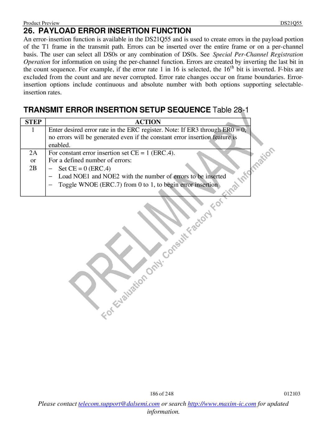
Payload Error Insertion Function
Transmit Error Insertion Setup Sequence Table
Step Action
ER3 ER2 ER1 ER0 Error Rate
Error Rate Control Register
Bits 0 to 3/Error Insertion Rate Select Bits ER0 to ER3
ERC
Value Write Read
Number Of Error Registers
Error Insertion Examples Table
NOE1
Number Of Errors Left Register
NOEL1
NOEL2
Channel Interleave Mode
Frame Interleave Mode
Interleaved PCM BUS Operation
Iboc
DA0 Device Position
IBS1 IBS0 BUS Size
IBO Example Figure
DS21Q55 #1 Rser DS21Q55 #3 Rser
Extended System Information BUS Esib
Esib Group of Four DS21Q55s Figure
B0h
ESIBCR1
Extended System Information Bus Control Register
ESIBSEL2 ESIBSEL1 ESIBSEL0 BUS BIT Driven
ESIBCR2
ESI3SEL2 ESI3SEL1 ESI3SEL0 Status Output T1 Mode E1 Mode
ESI4SEL2 ESI4SEL1 ESI4SEL0 Status Output T1 Mode E1 Mode
B1h
ESIB3
ESIB1
ESIB2
ESIB4
Programmable Backplane Clock Synthesizer
CCR2
BPCS1 BPCS0
72h
Fractional T1/E1 Support
CCR3
Tdatfmt Tgpcken Rdatfmt Rgpcken
JTAG-BOUNDARY-SCAN Architecture and TEST-ACCESS Port
Jtag Functional Block Diagram Figure
TAP Controller State Machine
Test-Logic-Reset
Update-DR
Run-Test-Idle
Capture-IR
Update-IR
Select-IR-Scan
Shift-IR
TAP Controller State Diagram Figure
Instruction Register
Instruction Codes for Ieee 1149.1 Architecture Table
Instruction Selected Register Instruction Codes
MSB LSB
ID Code Structure Table
Device ID Codes Table
Device BIT ID
Bypass Register
Test Registers
Boundary Scan Register
Identification Register
Rchblk Jtms Bpclk Jtclk Jtrst
BIT PIN Symbol Type Control BIT Description
Boundary Scan Control Bits Table
ESIBS0
Dvss Dvdd
Tsig Teso NXA Tdata NXA Tsysclk Tssync Tchclk
ESIBS1 MUX
Esibrd
Rsync RLOS/LOTC
Rsysclk
Receive Side ESF Timing Figure
Rclk
Rsysclk
Rsysclk Rser
Transmit Side D4 Timing Figure
Transmit Side ESF Timing Figure
Transmit Side Boundary Timing With Elastic Store Disabled
Tsysclk
TSER1
32.2 E1 Mode Receive Side Timing Figure
Receive Side Boundary Timing With Elastic Store Disabled
RSYNC2 Rmsync RSYNC3 Rchclk Rchblk
221 012103
Receive IBO Channel Interleave Mode Timing Figure
Receive IBO Frame Interleave Mode Timing Figure
TIMING, E1 Mode only Figure
Transmit Side Timing Figure
Tser LSB Si
Tssync Tchclk Tchblk
228 012103
Transmit IBO Channel Interleave Mode Timing Figure
Transmit IBO Frame Interleave Mode Timing Figure
Thermal Characteristics
Operating Parameters Absolute Maximum Ratings
THETA-JA θJA vs Airflow
Recommended DC Operating Conditions
DC Characteristics
Parameter Symbol MIN TYP MAX
Capacitance
AC Timing Parameters and Diagrams
Parameter Symbol MIN TYP MAX Units
Intel BUS Read Timing BTS = 0 / MUX = 1 Figure
Intel BUS Write Timing BTS = 0 / MUX = 1 Figure
Motorola BUS Timing BTS = 1 / MUX = 1 Figure
236 012103
Intel BUS Read Timing BTS = 0 / MUX = 0 Figure
Motorola BUS Read Timing BTS = 1 / MUX = 0 Figure
Receive Side AC Characteristics
AC CHARACTERISTICS-RECEIVE Side
Parameter Symbol MIN TYP MAX Units
Receive Side Timing T1 Mode Figure
Receive Side TIMING, Elastic Store Enabled T1 Mode Figure
Receive Line Interface Timing Figure
TYP E1
Transmit AC Characteristics
Parameter Symbol MIN
MAX Units
Tsysclk = 8.192MHz Tsysclk = 16.384MHz
Transmit Side TIMING, Elastic Store Enabled Figure
Transmit Line Interface Timing Figure
Mechanical Descriptions
Product Preview DS21Q55 248 012103