Diagnostics
B
4Diagnostics
Diagnostics are displayed on the
•Checking error states and signal integrity
•Identifying the cable terminal on the network
•Verify communications with the headend For the diagnostics described in this section:
•All indicators are in decimal notation, unless otherwise noted
•All
•All sample displays are illustrative; actual data may differ from the examples
Using the Diagnostics
To use the diagnostics:
1.Ensure that the QIP7000 series is installed with the Thin Client software and that it is connected to an AC outlet.
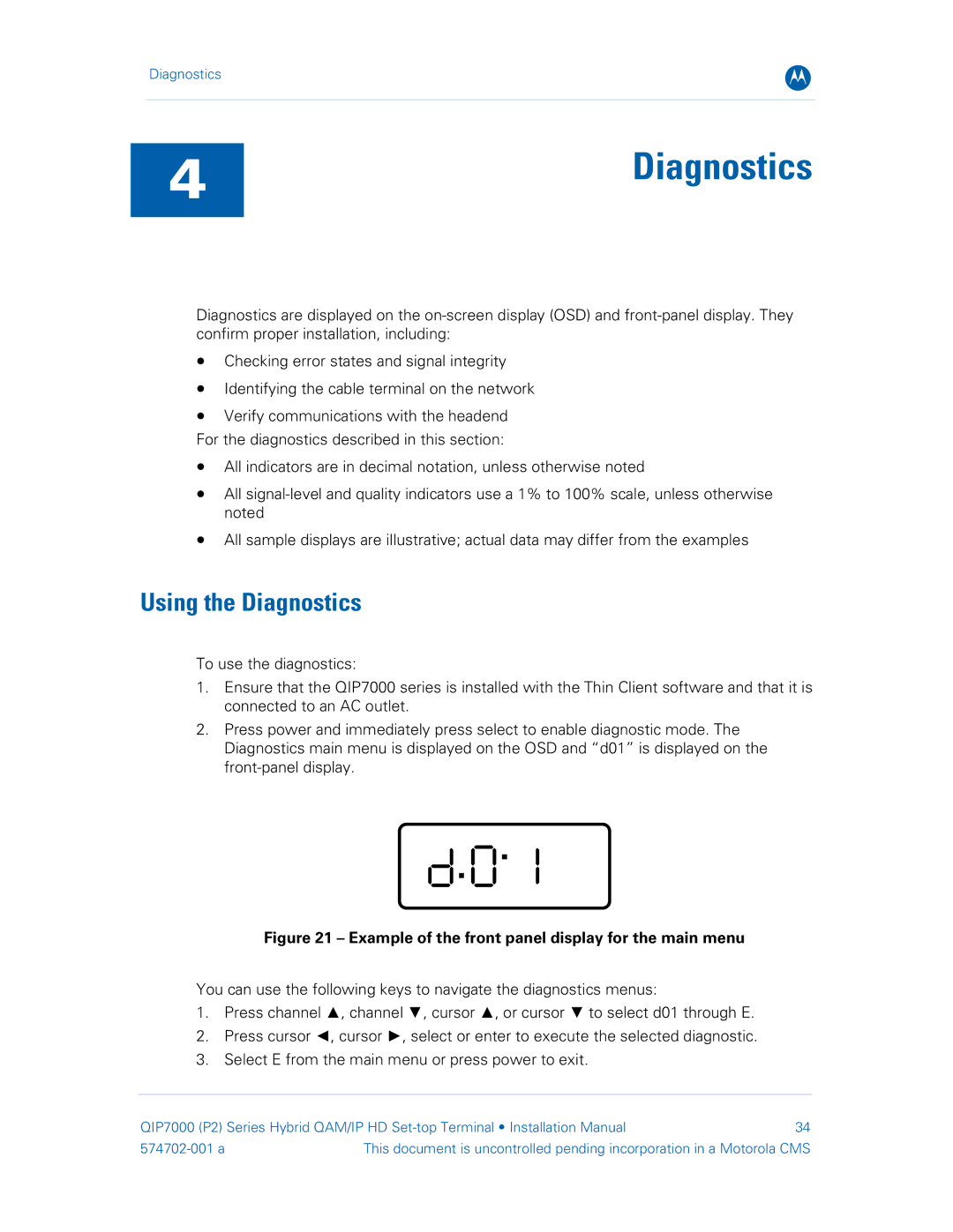
2.Press power and immediately press select to enable diagnostic mode. The Diagnostics main menu is displayed on the OSD and “d01” is displayed on the
Figure 21 – Example of the front panel display for the main menu
You can use the following keys to navigate the diagnostics menus:
1.Press channel ▲, channel ▼, cursor ▲, or cursor ▼ to select d01 through E.
2.Press cursor ◄, cursor ►, select or enter to execute the selected diagnostic.
3.Select E from the main menu or press power to exit.
QIP7000 (P2) Series Hybrid QAM/IP HD | 34 | |
This document is uncontrolled pending incorporation in a Motorola CMS | ||