Hybrid QAM/IP HD Set-top Terminal
Installation Manual
QIP7000 P2 Series
2009 Motorola, Inc. All rights reserved. No part of this publication may be reproduced in any form or by any means or used to make any derivative work such as translation, transformation, or adaptation without written permission from Motorola, Inc
IMPORTANT SAFETY INSTRUCTIONS
Safety and Compliance
Important Safety Considerations
During Transportation to the Subscriber Home
the user’s authority to operate the equipment
During Installation
FCC Compliance
Caring for the Environment by Recycling
FCC Declaration of Conformity
Canada Industry Canada IC
Safety and Compliance
Contents
Installation
Introduction
Tables
574702-001 a
Figures
1Introduction
Figure 2 - QIP7100 Front and rear views
Figure 1 - QIP7232 Front and rear views
Introduction
574702-001 a
Standard Audio/Video Features
Features
Tuners
Standard DVR Functionality Only available with the QIP7232
Table 1 - DVR Recording Time Guidelines
Standard Data Features
Standard Miscellaneous Features
Motorola Online http//businessonline.motorola.com
Getting Help
Calling for Repairs
Rear Panel
Front Panel
Figure 3 - QIP7232 front panel
Table 2 - Front panel
Figure 4 - Rear panel Table 3 - Rear panel connections
M-Card
Overview
Lable Description
Figure 5 - PON overview
System Overview
PON Overview
Whole Home IP Video Customer Premises Network-Embedded MoCA BHR
Figure 6 - Whole Home IP Video CPE overview
Figure 7 - MoCA RF spectrum
MoCA
Figure 8 - Multi room DVR network
Multi-Room DVR
Figure 10 - MoCA Set-Tops
Whole Home IP Video Network Installation
Installation
Installation
Before You Begin
During the installation
STB MAC
Figure 11 - QIP Set-Top MAC Addresses
Checking the Home Coaxial Network Topology
2. Optimize the high-definition settings
Table 4 - Sample table listing signal levels and MAC Addresses
Table 5 - QIP7000 series video outputs
Video Connection Options
can cause ingress
Clearing the Hard Drive
Audio Connection Options
network or satellite dish
Connecting to the ONT
Figure 12 - Connecting to the ONT1000
network or satellite dish
Connecting to the ONT with embedded MoCA
Figure 13 - Connecting to the ONT1000M
Installation
Table 6 - ONT1000M Connections
Name
Description
Connecting the Home Router - embedded MoCA ONT
Connecting Homes with Multiple Existing Cable Drops
Connecting the Home Router
Installation Overview
Figure 14 - Cabling to an HDTV
Cabling to an HDTV for Video
Figure 15 - Cabling to an HDTV for Audio
Cabling to an HDTV for Audio
Installation
574702-001 a
Figure 16 - Cabling to an HDTV and A/V Receiver for Video
Cabling to a High-Definition TV and an A/V Receiver for Video
Figure 17 - Cabling to an HDTV and A/V Receiver
Cabling to a High-Definition TV and an A/V Receiver for Audio
Figure 18 - Cabling to a Standard Definition stereo TV
Cabling to a Standard-Definition TV
Installation
574702-001 a
Figure 19 - Cabling to a Standard Definition TV, A/V Receiver and VCR
Cabling to a Standard-Definition TV, A/V Receiver and VCR
Figure 20 - Sample data devices you can connect to the QIP7000 series
Data Device Connections
Verifying the MoCA Network
Operational Check for the Remote Control
Optimizing the High-Definition Settings
To exit the setting and move to another setting, press the or key
Press the and keys to highlight the setting you wish to change
To exit the menu and save your settings, press the power or menu key
The User Settings menu options are
Setting Description
Installation
574702-001 a
This document is uncontrolled pending incorporation in a Motorola CMS
configured USER. Defaults to AUTO. Options are AUTO or USER
Graphics Overlaying the Video
Figure 21 - Example of the front panel display for the main menu
4Diagnostics
Using the Diagnostics
Diagnostics
d01 General Status
574702-001 a
This document is uncontrolled pending incorporation in a Motorola CMS
Diagnostics
Figure 22 - Example General Status display no error
Error code
code indicator
Error Code
Diagnostics
Field
Description
d02 Purchase Status
Figure 23 - Front panel display for Purchase Status diagnostic
Diagnostics
574702-001 a
The Purchase Status fields are
Diagnostics
Field
Description
d03 Out-Of-Band OOB Status
Figure 24 - Front panel display for the OOB diagnostic
Diagnostics
574702-001 a
Field
Diagnostics
Description
Front Panel
Agile OOB Tuner Hunting
Figure 25 - Front panel display for in band diagnostic
Figure 4-5 Front panel display for in-band diagnostic
d04 In-Band Status
Diagnostics
Field
Diagnostics
Description
Front Panel
Figure 26 - Front panel display of a unit address
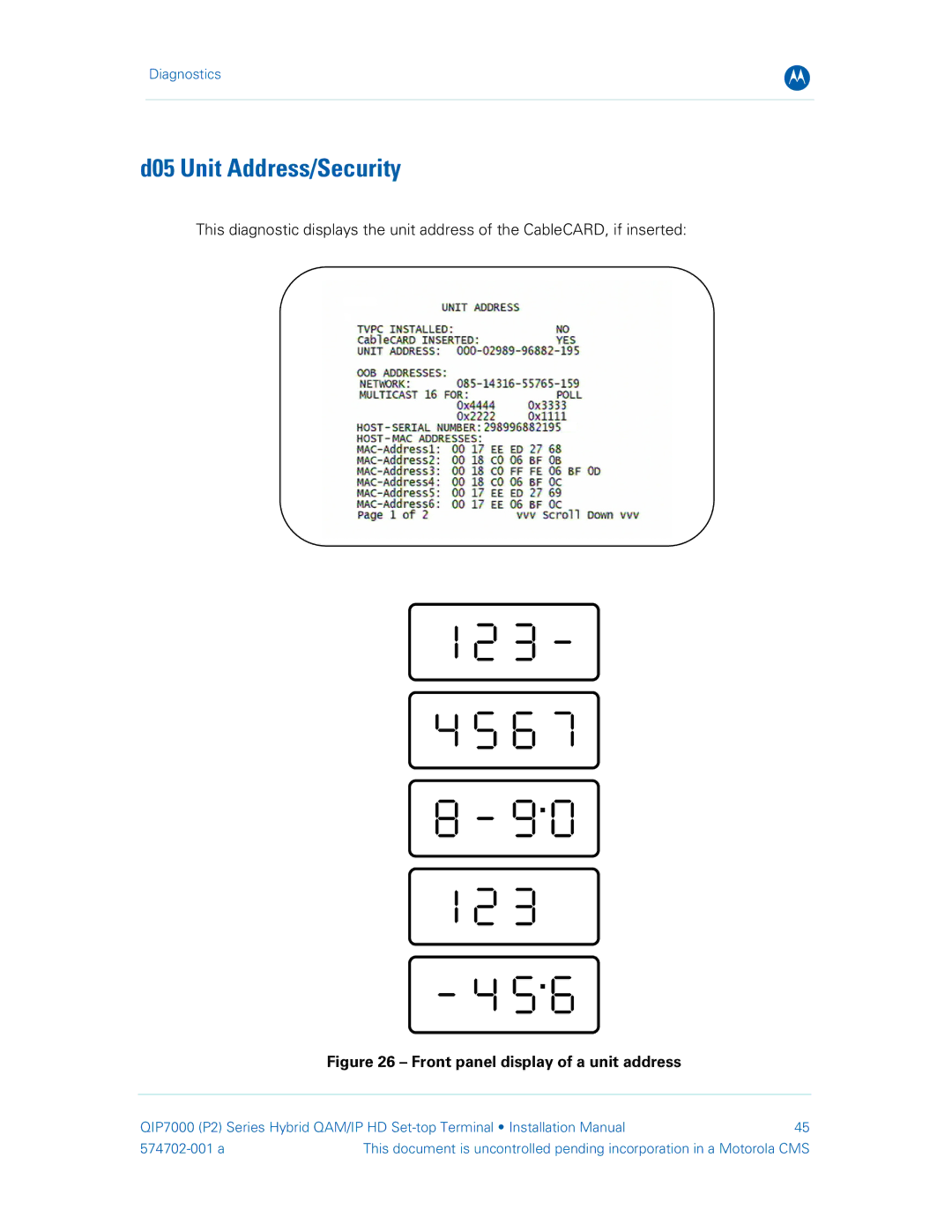
d05 Unit Address/Security
Diagnostics
574702-001 a
Diagnostics
Separable Security
Field
Description
The Separable Security fields are
Diagnostics
Field
Description
d06 Current Channel Status
Diagnostics
Figure 27 - Current channel status front panel displays
PurchasablePreview indicatorindicator
Epoch authorization
Field
Diagnostics
Description
Front Panel
Figure 28 - Ethernet Return front panel display
d07 Upstream Status
Diagnostics
574702-001 a
The Ethernet Return fields are
Diagnostics
Field
Description
d08 Code Modules
Diagnostics
Figure 29 - Front panel display for code modules
574702-001 a
This document is uncontrolled pending incorporation in a Motorola CMS
Field
Diagnostics
Description
Status
Note There is no front panel display for this diagnostic
d09 Memory Configuration
Diagnostics
Field
Diagnostics
d10 Audio/Video Status
Field
Description
Field
Diagnostics
Description
OSD Display
Field
Diagnostics
Description
574702-001 a
Diagnostics
d11 Interface/Port Status
574702-001 a
This document is uncontrolled pending incorporation in a Motorola CMS
Diagnostics
574702-001 a
The Interface Status fields are
Diagnostics
Field
Description
Diagnostics
d12 User Setting Status
Setting
Description
Setting
Diagnostics
Description
574702-001 a
This two-page diagnostic displays the DVR and hard-drive status
d13 DVR/Hard Drive Status
Diagnostics
574702-001 a
No - There is no over-temp problem
Diagnostics
The DVR/Hard Drive Status fields are
Field
Diagnostics
d14 Application Specific Information
Field
Description
Figure 30 - Interactive status front panel display
d15 Interactive Status
Diagnostics
Field
Field
Diagnostics
Description
574702-001 a
Diagnostics
d16 Connected Home
Field
Description
Table 7 - TX Data Rate
Diagnostics
d17 Key Pad / LED Test
574702-001 a
This document is uncontrolled pending incorporation in a Motorola CMS
Table 8 - Troubleshooting Guidelines
5Troubleshooting
Troubleshooting
Problem
Problem
Troubleshooting
Possible Solution
Note Closed captioning may not be available on the current program
Problem
Troubleshooting
Possible Solution
There are black bars above and below the picture
Insufficient RF Network Throughput
IP Network Issues
Bypassing an Amplifier
Figure 31 - Using a diplexer to bypass a line amplifier
574702-001 a 09/2009
Motorola, Inc 101 Tournament Drive Horsham, PA 19044 U.S.A