SBG940 User Guide
7
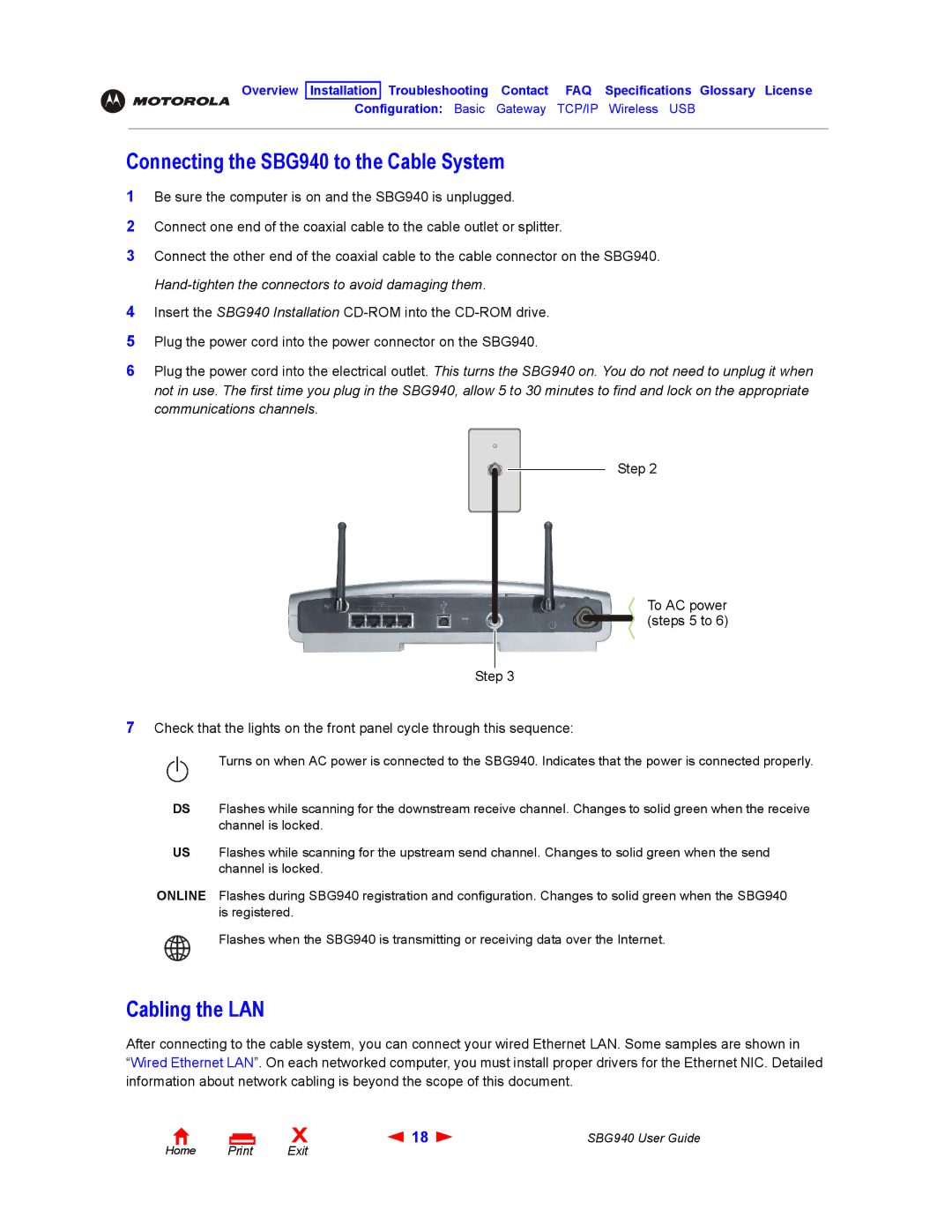
Step 3
Step 2
To AC power (steps 5 to 6)
1
2
3
USB
Flashes when the SBG940 is transmitting or receiving data over the Internet.
Cabling the LAN
After connecting to the cable system, you can connect your wired Ethernet LAN. Some samples are shown in
“Wired Ethernet LAN”. On each networked computer, you must install proper drivers for the Ethernet NIC. Detailed information about network cabling is beyond the scope of this document.
Flashes during SBG940 registration and configuration. Changes to solid green when the SBG940 is registered.
ONLINE
Flashes while scanning for the upstream send channel. Changes to solid green when the send channel is locked.
US
Flashes while scanning for the downstream receive channel. Changes to solid green when the receive channel is locked.
DS
Check that the lights on the front panel cycle through this sequence:
Turns on when AC power is connected to the SBG940. Indicates that the power is connected properly.
Plug the power cord into the power connector on the SBG940.
Insert the SBG940 Installation CD-ROM into the CD-ROM drive.
4
5
6 Plug the power cord into the electrical outlet. This turns the SBG940 on. You do not need to unplug it when not in use. The first time you plug in the SBG940, allow 5 to 30 minutes to find and lock on the appropriate communications channels.
Be sure the computer is on and the SBG940 is unplugged. Connect one end of the coaxial cable to the cable outlet or splitter.
Connect the other end of the coaxial cable to the cable connector on the SBG940. Hand-tighten the connectors to avoid damaging them.
Configuration: Basic Gateway TCP/IP Wireless
Connecting the SBG940 to the Cable System
Overview Installation Troubleshooting Contact FAQ Specifications Glossary License
Home Print
X![]() 18
18 ![]()