Canopy T1/E1 Multiplexer | September 2004 |
| T1/E1 Multiplexer FPGA Version 3.4 |
In a scenario where T1/E1 devices are configured with an external master clock source, each Canopy T1/E1 Multiplexer should be configured in Loopback Timing Mode. Each Canopy T1/E1 Multiplexer will take the timing signal from the incoming T1/E1, derive the clock and then return the clock to the T1/E1 device. The external clock source may be obtained from any number of sources including Carrier services, GPS, or other high- quality clock source.
For example, each of the two PBXs might have a SONET connection from the local telephone company operator. This connection would be used as the master clock source for both PBXs. Alternatively, each PBX could have a Stratum 3 clock source from the same Central Office, or could be connected to GPS receivers.
1.5.5Ethernet Throughput
The Ethernet port to the Canopy BH module is a
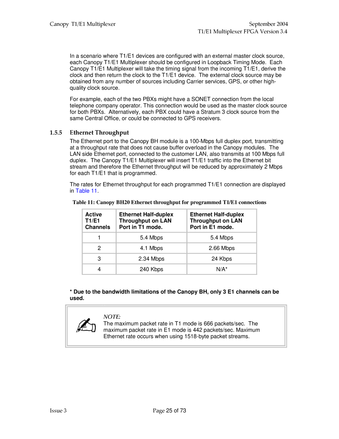
The rates for Ethernet throughput for each programmed T1/E1 connection are displayed in Table 11.
Table 11: Canopy BH20 Ethernet throughput for programmed T1/E1 connections
Active | Ethernet | Ethernet |
T1/E1 | Throughput on LAN | Throughput on LAN |
Channels | Port in T1 mode. | Port in E1 mode. |
1 | 5.4 Mbps | 5.4 Mbps |
|
|
|
2 | 4.1 Mbps | 2.66 Mbps |
|
|
|
3 | 2.34 Mbps | 24 Kbps |
|
|
|
4 | 240 Kbps | N/A* |
|
|
|
*Due to the bandwidth limitations of the Canopy BH, only 3 E1 channels can be used.
NOTE:
The maximum packet rate in T1 mode is 666 packets/sec. The maximum packet rate in E1 mode is 442 packets/sec. Maximum Ethernet rate occurs when using
Issue 3 | Page 25 of 73 |
