Canopy T1/E1 Multiplexer | September 2004 |
| T1/E1 Multiplexer FPGA Version 3.4 |
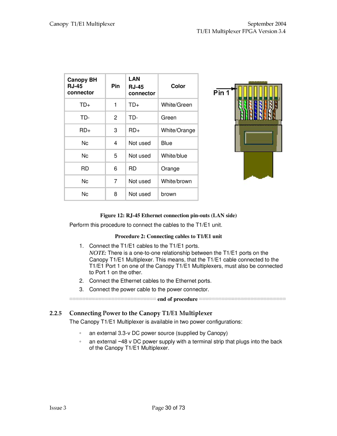
Canopy BH | Pin | LAN | Color |
| |||
connector |
| connector |
|
TD+ | 1 | TD+ | White/Green |
|
|
|
|
TD- | 2 | TD- | Green |
|
|
|
|
RD+ | 3 | RD+ | White/Orange |
|
|
|
|
Nc | 4 | Not used | Blue |
|
|
|
|
Nc | 5 | Not used | White/blue |
|
|
|
|
RD | 6 | RD | Orange |
|
|
|
|
Nc | 7 | Not used | White/brown |
|
|
|
|
Nc | 8 | Not used | brown |
|
|
|
|
Figure 12: RJ-45 Ethernet connection pin-outs (LAN side)
Perform this procedure to connect the cables to the T1/E1 unit.
Procedure 2: Connecting cables to T1/E1 unit
1.Connect the T1/E1 cables to the T1/E1 ports.
NOTE: There is a
2.Connect the Ethernet cables to the Ethernet ports.
3.Connect the power cable to the power connector.


 end of procedure


2.2.5Connecting Power to the Canopy T1/E1 Multiplexer
The Canopy T1/E1 Multiplexer is available in two power configurations:
◦an external
◦an external −48 v DC power supply with a terminal strip that plugs into the back of the Canopy T1/E1 Multiplexer.
Issue 3 | Page 30 of 73 |