MAINTENANCE PROCEDURE
3.4 Fault Repair Procedure for Analog CCIS Line
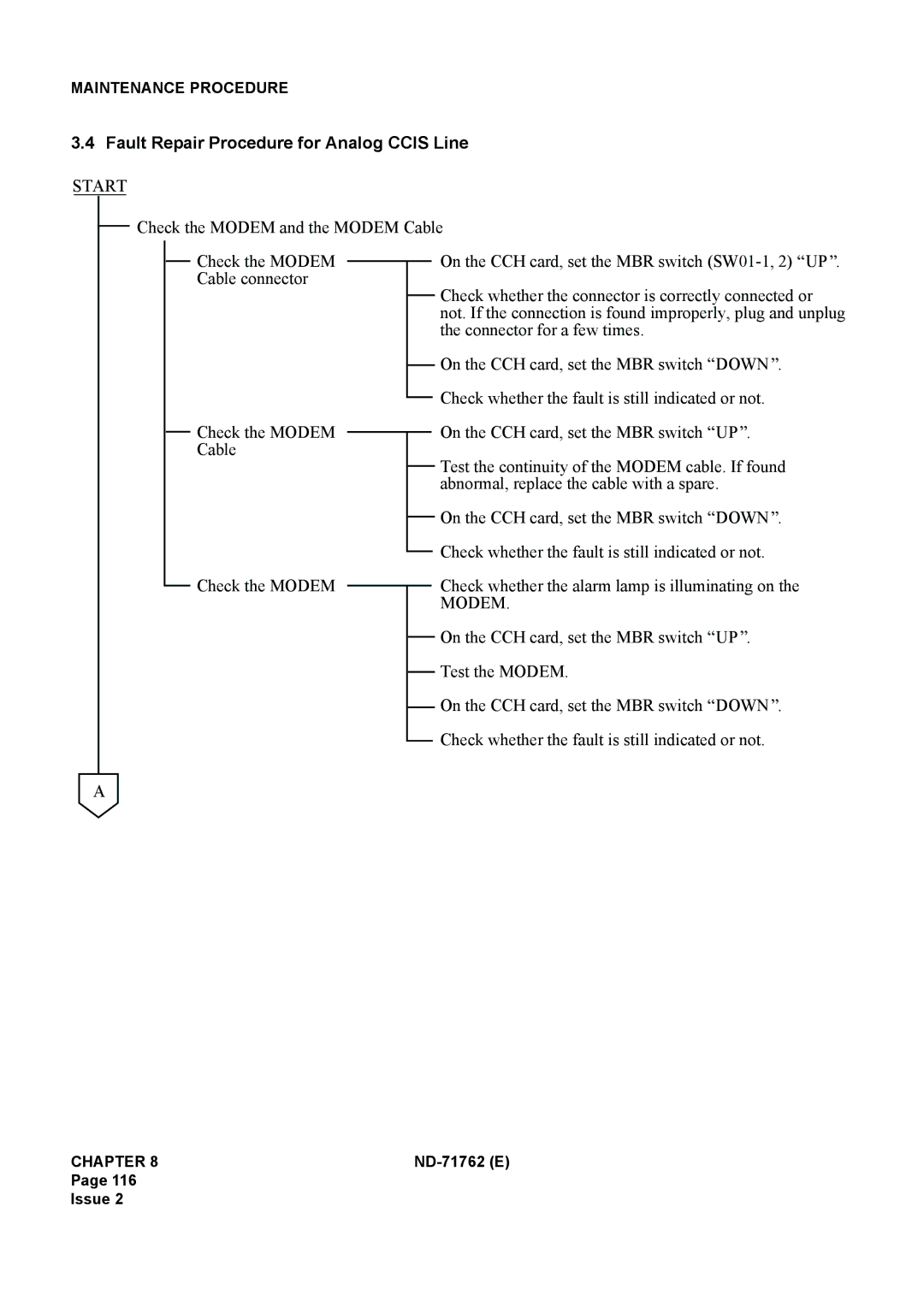
START
Check the MODEM and the MODEM Cable
Check the MODEM Cable connector
Check the MODEM Cable
Check the MODEM
On the CCH card, set the MBR switch ![]() UP
UP![]() .
.
Check whether the connector is correctly connected or not. If the connection is found improperly, plug and unplug the connector for a few times.
On the CCH card, set the MBR switch ![]() DOWN
DOWN![]() .
.
Check whether the fault is still indicated or not.
On the CCH card, set the MBR switch ![]() UP
UP![]() .
.
Test the continuity of the MODEM cable. If found abnormal, replace the cable with a spare.
On the CCH card, set the MBR switch ![]() DOWN
DOWN![]() .
.
Check whether the fault is still indicated or not.
Check whether the alarm lamp is illuminating on the
MODEM.
On the CCH card, set the MBR switch ![]() UP
UP![]() .
.
Test the MODEM.
On the CCH card, set the MBR switch ![]() DOWN
DOWN![]() .
.
Check whether the fault is still indicated or not.
A
CHAPTER 8 |
|
Page 116
Issue 2