GENERAL INFORMATION FOR CCIS
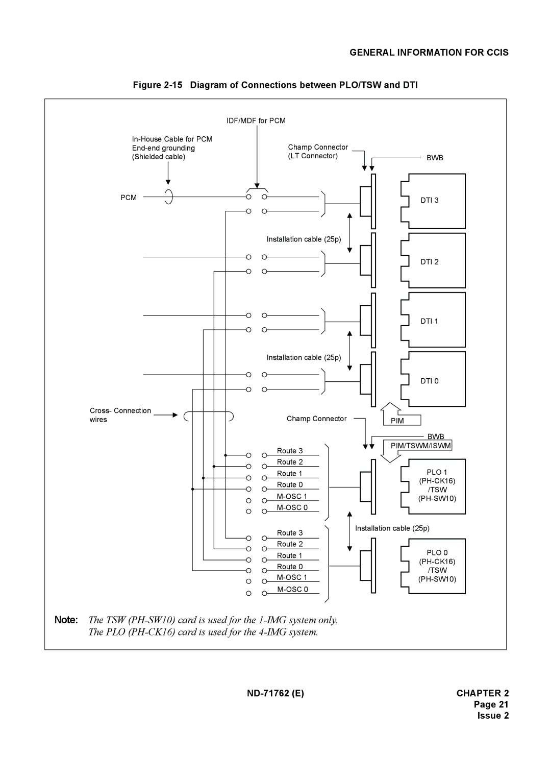
Figure 2-15 Diagram of Connections between PLO/TSW and DTI
IDF/MDF for PCM
Champ Connector | |
(Shielded cable) | (LT Connector) |
PCM
Installation cable (25p)
| Installation cable (25p) |
Cross- Connection | Champ Connector |
wires | |
| Route 3 |
| Route 2 |
| Route 1 |
| Route 0 |
| |
| |
| Route 3 |
| Route 2 |
| Route 1 |
| Route 0 |
| |
|
BWB
DTI 3
DTI 2
DTI 1
DTI 0
PIM
BWB
PIM/TSWM/ISWM
PLO 1
/TSW
Installation cable (25p)
PLO 0
/TSW
Note: The TSW
Page 21
Issue 2