GENERAL INFORMATION FOR CCIS
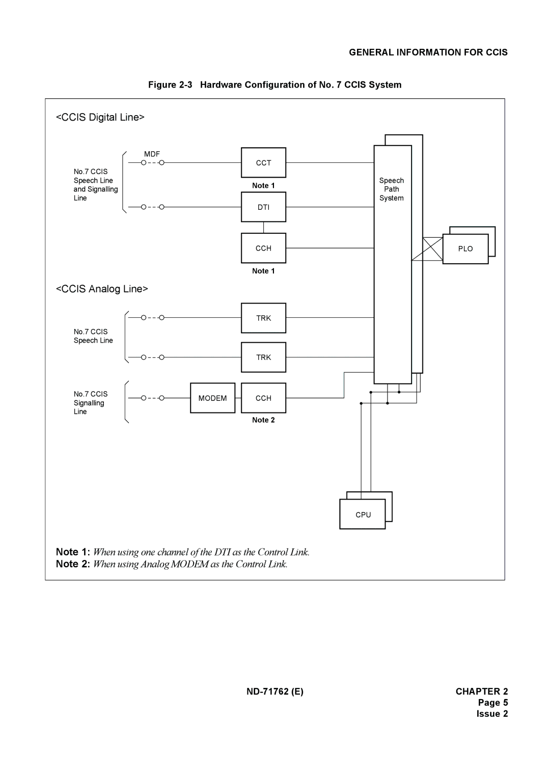
Figure 2-3 Hardware Configuration of No. 7 CCIS System
<CCIS Digital Line>
MDF
No.7 CCIS
Speech Line
and Signalling
Line
<CCIS Analog Line>
No.7 CCIS
Speech Line
No.7 CCIS
Signalling
Line
MODEM
CCT
Note 1
DTI
CCH
Note 1
TRK
TRK
CCH
Note 2
Speech
Path
System
PLO
CPU
Note 1: When using one channel of the DTI as the Control Link.
Note 2: When using Analog MODEM as the Control Link.
Page 5
Issue 2