Manuals
/
NEC
/
Communications
/
Telephone
NEC
ND-71762(E)
system manual
Circuit Card Mounting Partial Insertion
Models:
ND-71762(E)
1
48
138
138
Download
138 pages
23.8 Kb
45
46
47
48
49
50
51
52
Install
END Fault Supervision
Maintenance
Network Configuration
ND-71762 E Issue
Command Name Asyd
Procedure a
Switch Setting Sheets
How to
Safety
Page 48
Image 48
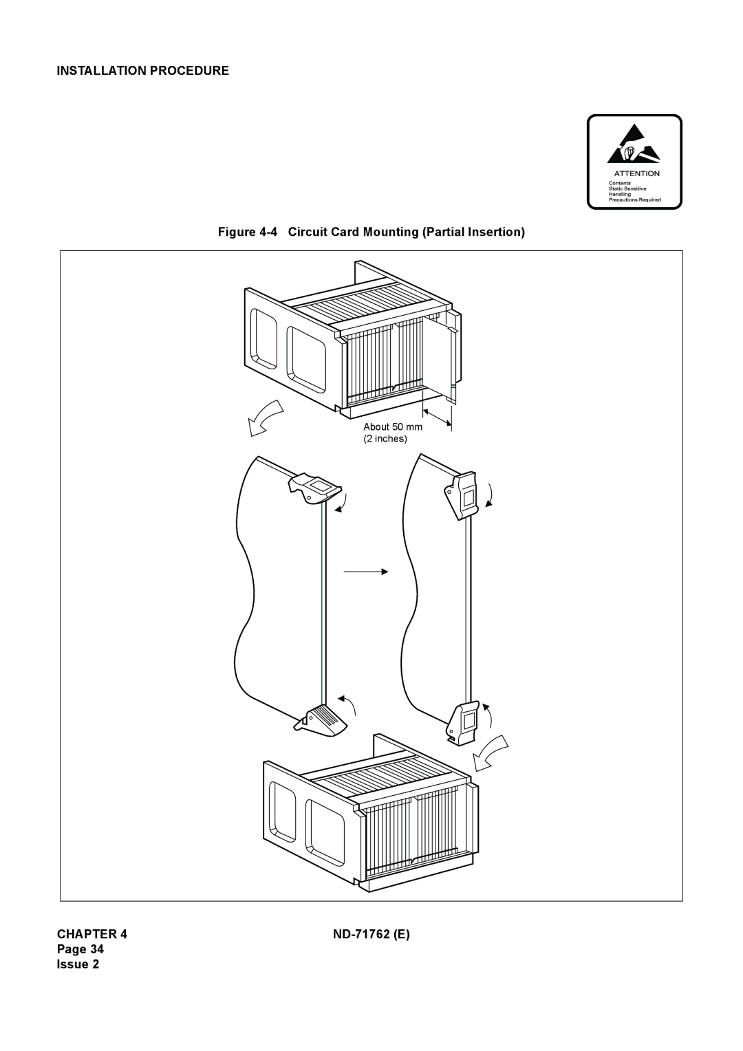
INSTALLATION PROCEDURE
Figure
4-4
Circuit Card Mounting (Partial Insertion)
About 50 mm (2 inches)
CHAPTER 4
ND-71762
(E)
Page 34
Issue 2
Page 47
Page 49
Page 48
Image 48
Page 47
Page 49
Contents
NEC Corporation
Liability Disclaimer
For Safety USE
Before the USE of this Manual
ND-71762 E
ND-71762 Eproduct Liability PL- 3 Issue
Product Liability
ND-71762 Eproduct Liability PL- 5 Issue
Thinner
ND-71762 Eproduct Liability PL- 7 Issue
This page is for your notes
Table of Contents
Internet Protocol eXchange
ND-71762 E Issue
ND-71762 Etable of Contents Page iii Issue
This page is for your notes
HOW to Follow the Manual
Configuration of the No Ccis System Manual
General
General Information for Ccis
Description of Ccis
Centralized Facilities Centralized Management
System Configuration 3.1 Outline
Modem
Ccis Digital Line
Network Configuration
PBX DTI CCH CCT ATI COT
Example of Network Configuration for Ccis Analog Line
Types of Network
Type MAIN-SATELLITE Network MAIN-REMOTE/CAMPUS Remarks
Nationwide Corporation
Campus Configuration
University/Campus Environment
Main-Remote Configuration
Manufacturing/Plant Environment
Associated Mode
Ccis Network Modes
Quasi-Associated Mode
Ccis Network Redundancy
Digital Network and Network Synchronization 5.1 Outline
Office Ranks and Kind of Oscillator
⋅ Applicable Not Applicable
Office Rank Source Office
PLO ACT OSC
12 Clock Extraction and Backup Routes
Sub-Source Office
Receiver Office and Local Receiver Office
13 shows the routes for clock extraction
Clock Pulses from M-OSC/EXT. OSC and Connection with PLO/OSC
Clocks Extracted from DTI and Connection of PLO/TSW
15 Diagram of Connections between PLO/TSW and DTI
16 Route Automatic Changeover Priority Order DCS connection
General Information for Ccis
⋅ Normal Fault Clock Down, etc Normal or Faulty
Centralized MAT
IPX Neax 2400 IPX
Conditions for Network Establishment
IPS IPX
IPX IPX
Fccs Group FUG
FUG1
FUG3
Interactions
Switch Setting Sheets
List of Circuit Cards
Installation Procedure
Precautions on Installation
Static Caution Indication
Installation Procedure
General Flow of Installation Procedure
Start
MDF
Start
Circuit Card Mounting Partial Insertion
TSW Note card and the terminal
LT Connector Leads Accommodation for DTI/CCT
PLO Pin Assignments for Receiving Clock 1-IMG System
PLO Pin Assignment for Receiving Clock 4-IMG System
TSW PLO
ISW
PBX
IMG
Front Cable Connection between DTI and CCH
12 Front Cable Connections between DTI/CCT and CCH
Cable Running from PBX to the Modem for Analog Ccis Line
13 Connection of Modem Cables for Analog Ccis Line
14 Connecting Route Diagram for CCH
Cable Connection when Accommodated in *1 Refer to Figure
Cable Connection when Accommodated in *3. Refer to Figure
Accommodated in *1 Accommodated in *2 Accommodated in *3
Installation Test Procedure
Overall Test of Ccis Tie Line Outgoing Call
Attcon
Procedure a
Overall Test of Ccis Tie Line Incoming Call
Test of Connection and Alternate Routing to All Tie Lines
Combination of Tie Line Network and Public Network
Test of Tandem Connection to Tie Line
PBX Alternate Route PBX Station B Station C
END
PAD Setting
Example
Ccis Service Feature Functional Test
Test of Interoffice Station to Station Connection
Test of Outgoing Call Connection to Tie Line Trunk
Test of Transfer Services
Test of Services from Attcon
Test of other Services
Test Result Report
Smds
Test of Services from Attcon
Basic Data Assignment
Port Allocation and Related Command
Data Assignment
Basic Data Assignment Procedure
CCH2 Ccccc
Command Name Asyd
Step
Issue 07/31/02
Command Name
Command Name Arsc & Arrc
ACC
CI N/H SRV LCR
Command Name Atrk & Mbtk
Command Name Adpc
Step Command Name
Acsc
Command Name ACIC1
Command Name ACIC2
Sample office data assignment sheet for Node a is as follows
Fccs Data Assignment Procedure
LRT → PC → Cscg → CCH
PC → Cscg → CCH
FUG + FPC → PC → Cscg → CCH
Basic Data Assignment
Basic Data Assignment
PC2 LGRT1
IMX LN
Basic Data Assignment
Ccis Service Features
Service Function Name Remarks
List of Service Features for Ccis 2/2 Service Code No
Maintenance Procedure
System Messages
Relationship between System Messages and Lamp Indications
System Message
Name
PWR
Phase 1 Restart Processing Execution
Phase 3 Restart Processing Execution
Technical Terms for Explaining Message Detail Data
Data for Analysis by NEC Engineers
MG and Unit configuration IMG/4-IMG system
Circuit Card Mounting Information
Group Configuration
How to Proceed with Diagnostic Work from System Message
END Fault Supervision
Fault Check of Work
System Messages
MAY 14 LP00-0-ACT XX00 0000 0000 0000 0000 0000
Supervision Fault
Maintenance Procedure
Start
Maintenance Procedure
Fault
On OFF
Maintenance Procedure
Start
CCH B-Level Infinite Loop Failure Permanent Meaning
Displayed again Paragraphs 3.3 or System Message 13-F
Maintenance Procedure
Start
Digital Ccis Line
System Message 13-H SUP CCS Link Failure Permanent NEC Tokyo
Start
System Message 13-I NON CCS Link Failure Temporary NEC Tokyo
CCH/CCT circuit card is faulty Paragraphs 3.3 or
MAY 14 LP00-0-ACT XX XX 0000 0000 0000 0000 0000
MAY 14 LP00-0-ACT XX00 0000 0000 0000 0000 0000
CCH/CCT card is faulty. Paragraphs 3.3 or
System Message 17-A NON CCH MBR KEY Turn on NEC Tokyo
System Message 17-B NON CCH MBR KEY Turn OFF NEC Tokyo
Ccis Common Channel Interoffice Signaling Line Fault
Check Point
Ccis Line Control
Fault Repair Procedure for Digital Ccis Line
Start
Fault Repair Procedure for Analog Ccis Line
Modem
Check by replacing the CCH card with spare
Ccis Line Operating Mode Control
INSERTION/EXTRACTION of Circuit Cards
CCH Circuit Card
DTI Circuit Card
CCT Circuit Card
PLO/OSC Circuit Card
ND-71762E
Issue No 103 104
Top
Page
Image
Contents