GENERAL INFORMATION FOR CCIS
4.3.2Quasi-Associated Mode
In Figure
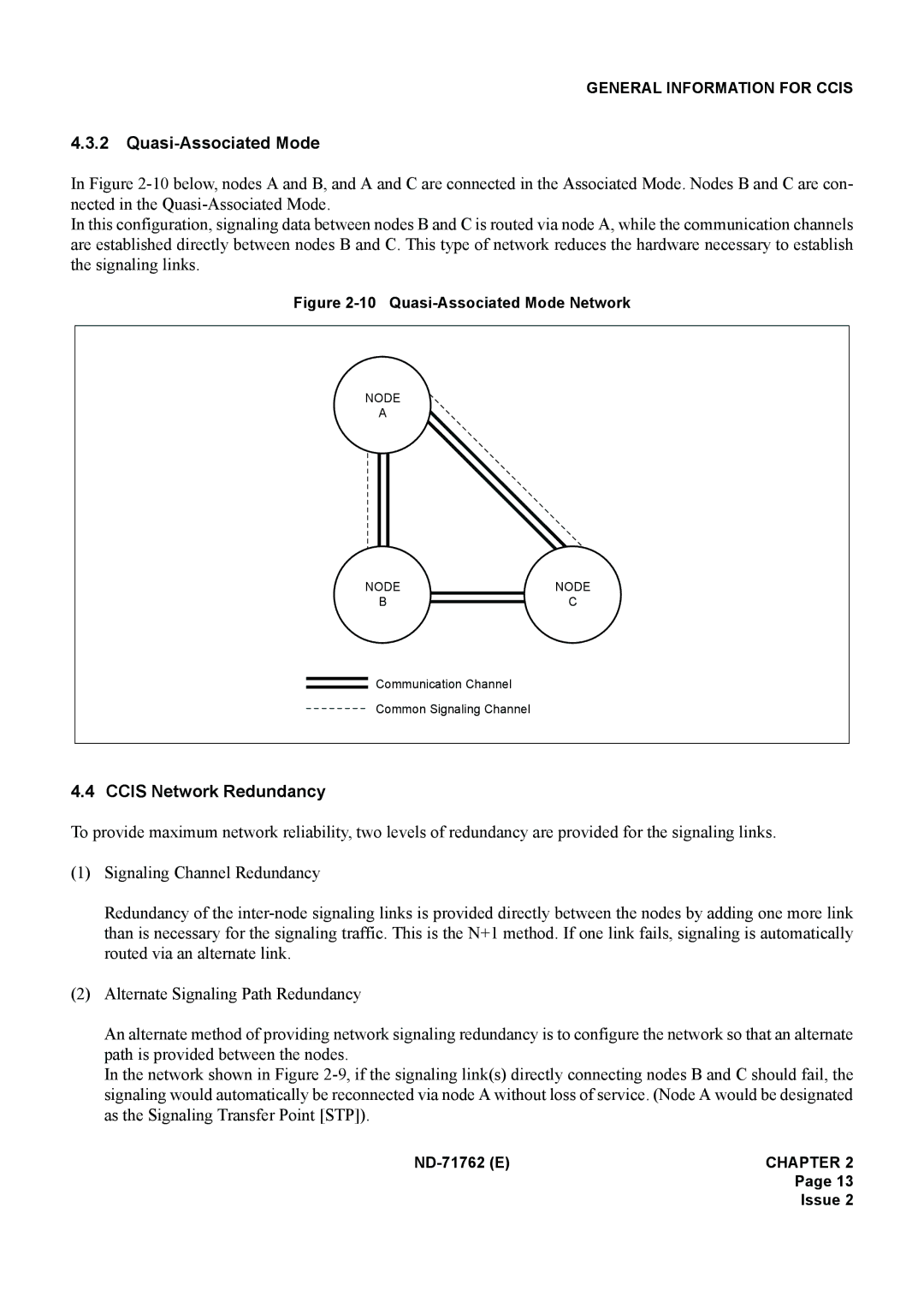
In this configuration, signaling data between nodes B and C is routed via node A, while the communication channels are established directly between nodes B and C. This type of network reduces the hardware necessary to establish the signaling links.
Figure 2-10 Quasi-Associated Mode Network
NODE
A
NODE | NODE |
B | C |
Communication Channel
Common Signaling Channel
4.4 CCIS Network Redundancy
To provide maximum network reliability, two levels of redundancy are provided for the signaling links.
(1)Signaling Channel Redundancy
Redundancy of the
(2)Alternate Signaling Path Redundancy
An alternate method of providing network signaling redundancy is to configure the network so that an alternate path is provided between the nodes.
In the network shown in Figure
Page 13
Issue 2