Mainframe AV-HS450U1N
Control panel AV-HS450C1N
Safety precautions
FCC Note
Important Safety Instructions
For USA-California Only
Contents
Input/output signal settings
System settings 131
Features
Compact design, wide variety of input/output signals
Description
Multiple formats supported
High-quality chroma keys using Primatte algorithms
Redundant power supply
Many different effect functions incorporated
Sdhc memory cards supported
Configuration
Accessories
Optional boards sold separately
Board
Precautions for use
Trademarks and Registered Trademarks
Installation
Installing the control panel
Choosing the best installation location
Handle the control panel carefully
Support guides
Installing the mainframe
Handle the mainframe carefully
Blank panel Screw
How to install the option boards
Slot a Slot B
UTS INP DVI
Mainframe
Block diagram
Connections
AV-HS450N
HD SDI
HD SDI VTR
DVI-D
Example where the optional board is used
DVD player
VTR HD SDI SD SDI
AC adapter PC monitor
Power indicator Power
Alarm indicator Alarm
Functions in each area
Control panel
PST/B bus crosspoint buttons PST/B 1 to
Crosspoint area
PGM/A bus crosspoint buttons PGM/A 1 to
Pattern page indicator LEDs
Wipe pattern/memory area
AUX bus crosspoint buttons
Wipe pattern and memory selector buttons
User button area
Transition area
MIX button
Wipe button
Auto button
CUT button
Bus tally LEDs
Wipe direction selection buttons Wipe Direction N/R, R
Fader lever
LCD menu area
List of menu delegation functions
Menu function buttons Menu FUNCTION/AUX BUS Delegation
Rotary encoders F1 to F5
Hold button
Basic menu operations
Positioner area
Positioner X/Y
Rotary encoder Z
Wipe Bkgd
SD memory card access LED
SD memory card area
SD memory card slot
SD memory cards
Rear panel connections area
Power switch POWER1, POWER2
Power indicator POWER1, POWER2
Alarm indicator ALARM1, ALARM2
Mainframe
SDI signal input connectors SDI Inputs 1 to
SDI signal output connectors SDI Outputs 1 to
DVI-D output connectors DVI-D Outputs 5
Reference input connector/BB output connector REF
LAN connector LAN RJ-45 10/100 Base-TX
Ground connector Signal GND
AC power input socket IN1 IN2 AC 100 V to 120 V, 50/60 Hz
Cooling fan
Selecting the bus using the Shift function
Basic operations
Background transition
Selecting the bus
All Shift
Single Shift
Allocating the Shift function
Menu display
Basic operations
Selecting the bus mode
PGM PGM/A PGM/A, PST/B PVW PST
Selecting the transition mode
Manual transition using the fader lever
Auto transition
Cut transition
Setting the Image effects
Image
Executing the Image effect
How to select the wipe patterns
Wipe
Selecting the wipe pattern
Table of wipe patterns
SL SL
SQ2 squeeze
SQ SQ
Selecting the background for the 3D2 pattern
Selecting the wipe direction
Setting the border and soft effect
Setting the border color
To call the preset color
Wipe decorations border, soft effect
Setting the wipe start position
Pos, Y-Pos setting range
Setting the lighting effect
Modifying wipe
For background transitions
For key transitions
Setting the trimming
Key
Selecting the key type
Lum luminance key/self key
Linear linear key/EXT key
Chroma chroma key/self key
Selecting the key fill signal
Selecting the key source signal
Setting with AUX bus crosspoint buttons
Setting in the Config menu
Key transitions
Pattern examples
Key preview
Key auto transition
Adjusting the luminance key and linear key
Operation Parameter Description of setting Setting range
To execute the sampling manually
Adjusting the chroma key
Step To execute the sampling automatically
Step
Sample1 Matte Cln.FG
Sample1 CmpsitSpl.Spg
Chrkey 3 View Mode
Matte
Spill- Spill+
Spill Matte- Matte+
Detail- Detail+
Detail MatSpng
MkFGTrn
RstrDtl
FineTun
Key decorations
Setting the key edge
Setting the edge color
Masking the key signals
Turn F2 to F5 to set the area to be masked
PinP combinations using the flying key
Flying key
PinP picture in picture
Selecting the PinP channel and material
Selecting Shape
PinP preview
PinP transitions
PinP adjustments
Adjusting the PinP position and size
Adjusting the rotation angle
Select the dot by dot mode
Linking PinP1 and PinP2
Setting the priority
Linking PinP1 and PinP2
PinP decorations
Trimming settings
DSK downstream key
Selecting the DSK type
Setting the fill matte color
Selecting the DSK source signal
Selecting the DSK channel and DSK fill material
DSK transitions
DSK preview
DSK adjustments
DSK decorations
Masking the DSK signals
FTB fade to black
Internal color signals
Setting the color background
Adjusting the colors
Calling the preset colors
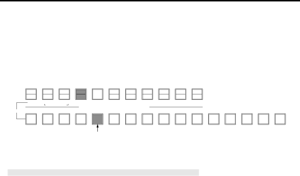
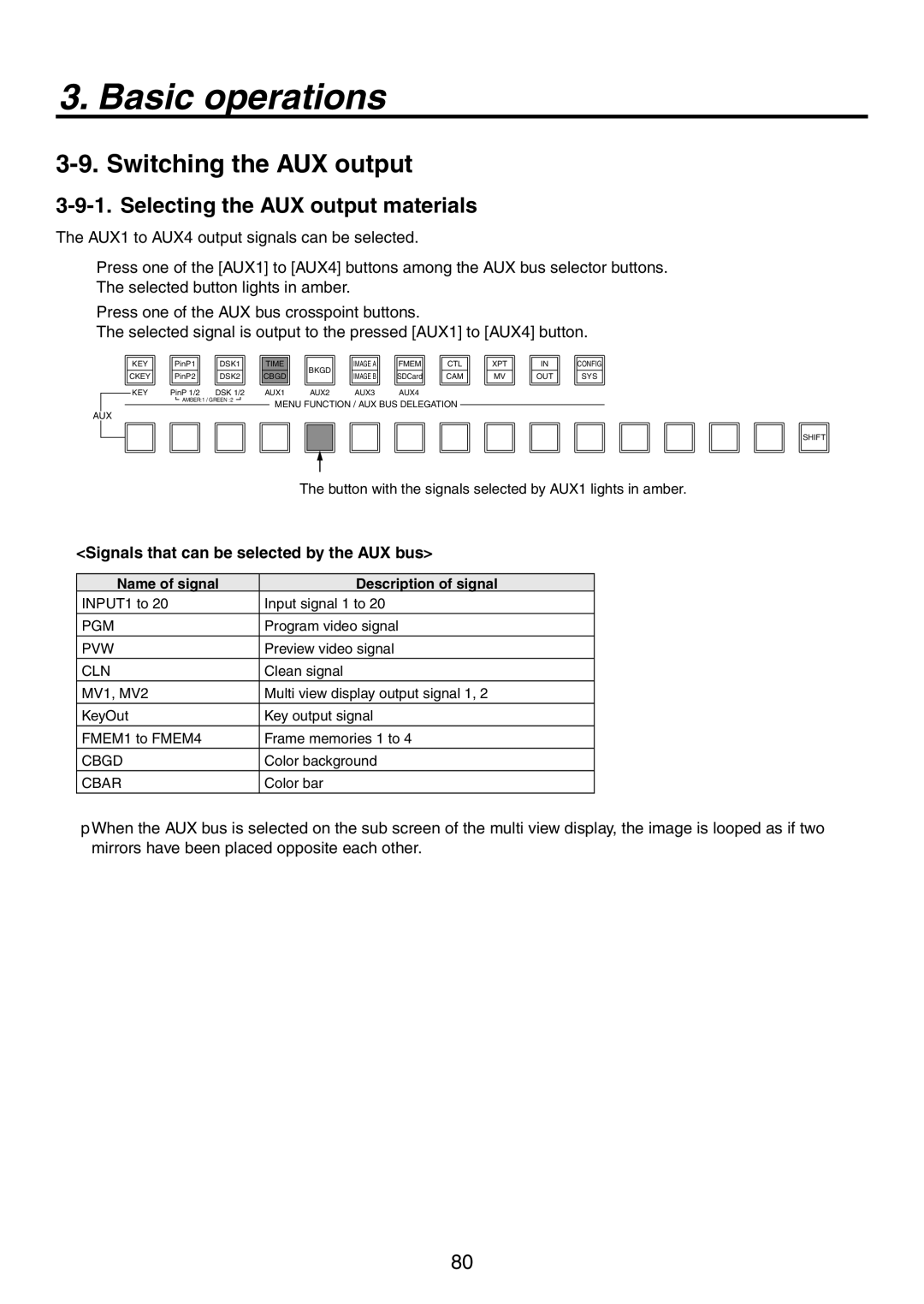
Switching the AUX output
Signals that can be selected by the AUX bus
Name of signal Description of signal
Selecting the AUX output materials
AUX1 transitions
Setting enable/disable for the AUX1 transition
Enable Enable Disable Disable
Memory
Memory registration and recall items
Material selected Transition Pattern Menu
Storing the settings in the memory Store
Recalling the operations stored in the memory Recall
Recall
Deleting the operations stored in the memory Delete
Effect dissolve
Frame memories
Transferring images from the AUX bus
Saving Images in Flash Memory
SD memory cards
Initializing the SD memory cards
Saving data on SD memory cards
SetUp
Configuration of folder at storage destination
Loading data from SD memory cards
Characters which can be used for filenames
Deleting files on SD memory cards
Displaying the SD memory card information
List of settings by input signal
Input/output signal settings
Input signal settings
Setting the frame synchronizer
Setting the input mode
List of input modes supported
Freezing the input signals
Setting freeze
Color corrector
Enabling the color corrector
Adjusting the gain and hue of the C signal
Input level
Tone curve
Output level
Adjusting the color matrix item gain
Setting the up-converter
Input image
Setting the analog input gain option
Fine-tuning of image positions
Setting the analog composite input signals option
Setting the DVI input signals option
Setting the DVI input signals
DVI Input Board Digital/Analog
Full-HD DVI Input Board Digital
Initializing the adjusted values
Automatic adjustment of the black level
Automatic adjustment of the white level
1920 1280 720
Fit-V
1024 768
Fit-H
DVI format Mode HD/1080i HD/720P
1680 1050
1600 1200
1920 1200
Adjusting the DVI input signals
Input XX DVIPhs ClkPhs H-Pos −16 −100
Setting the output signals
List of settings by output signal
Manual Output connector Asign
DownCnv Dig
Assigning the output signals
Assigning the CLN signal
DC down-converter
115
116
Setting the down-converter option
SQ squeeze
EC edge crop
LB letter box
Setting the sync signals
Adjusting the output signal phase
Phase adjustment setup
Signals
Frame synchronizer
Input
Video effects
Phase relationship between input signals and output signals
For 1080/59.94i format Example
Setting the multi view display
Setting the screen layout
Name of signal Display on LCD
Setting the split frame and characters
LUM 0%, 25%, 50%, 75%, 100%
Setting the tally displays
Changing the material names
Preset type setting procedure
User type setting procedure
High-resolution multi view mode
Setting the on-screen display OSD
Examples of OSD displays
Setting the embedded audio data
Setting the ancillary data
Setting the V ancillary data
Selecting the video format
System settings
Setting the 169 squeeze mode
Setting the crosspoints
Assigning signals to the crosspoints
Assigning signals to the crosspoints
Displaying the assignment statuses
Button Signal Description
Button Signal
Setting the crosspoint switching
Function name Description of function
Setting the user buttons
Button assignments
Setting method
Shift
Setting the time
Setting the date and time
Setting the date
Network settings
Setting the IP address
Setting the subnet mask
Display the MAC address
Other settings
Setting the LCD backlight
Menu delegation settings
60, 120
Enable/Disable Setting for Control of External Devices
External device control
GVG AV-HS450N
Editor control
Table of wipe patterns supported
TALLY/GPI connector of control panel
Setting the GPI
TALLY/GPI connector of mainframe
Control using the GPI input port
Output from the GPI output port
Assign Item Description of function assigned Control method
Assign Item Description of function assigned Output
Camera control
Functions that can be controlled from the unit
Connection specifications
AW-RP655N
Connections for AW-HE100N, AW-PH405N or AW-PH360N
AW-HE100N, AW-PH405N, AW-PH360N Pin No
AW-IF400G Switch settings
SW1 SW2 SET UP OFF
Connections for AW-PH400P
AV-HS450N AW-PH400P
Camera control settings
CAM CTL
PanTilt and Zm/Focs
For controlling the lens Zooming
Changing values
Operation of F5 in the setup screen Selecting Yes/No
Cameras menu operations
Alarm status displays
Alarm message
Alarm message displayed Type of trouble Operation
Status displays
Displaying the version information and option information
Initializing Fader
Initializing Setting Data
Initialization
LAN
Connecting the control panel and mainframe
External interfaces
Editor
COM
Example of GPI Out and Alarm connections
TALLY/GPI
Example of GPI In connections
Sub 50-pin, female, inch screw
Tally LED
Sub 25-pin, female, inch screw
Max. current 50 mA
Specifications
Image transmission functions
Connections
LAN cable
How to install the software
Setting the IP address
Operation
Startup
Exit
Transmitting images to the unit
Transmitting images from the unit
PVW
Setting menu table
Parameter
Undo ↓
Reset ↓
CHR KEY Chrkey
Trim Manual
Left Top Bottom Right TrimAdj
Prior Synm Sync
PinP2
DSK2
DSK1
Hue Sat Lum Load ↓
AUX1
Time
Enbl
Cbgd
EFF Dslv
FTB
Imag a IMG a
Imag a
Imag B IMG B
Imag B
CAM
XPT
Split Pos Signal
MV1 Patt
Frame Char Label Tally MV1Frame
MV2 Patt
Input
SDI
Clear ↓
RGB
ANA
DVI
Output Outputyy
DVI-I
Config
LCD-BL Menudlg
Shot MEM
Enbl Sysconf
GPIP-In
GPIP-Out
CONFIG10
CONFIG11
CONFIG12
USER1 USER2 USER3
System
System SYS
SYS
Select Version SysVer
MainVer
Select Board Version OptVer
Appearance
Mainframe
Unit inch mm
Control panel
Specifications
Mainframe AV-HS450U1N
SDI outputs
Composite input
Option
Analog input
Video delay time
DVI-D input
DVI-D output
Reference
Temperature Humidity
Power supply
Dimensions
Weight
Supplied power cord
Control panel AV-HS450C1N
External media
Supplied AC adaptor
Appendix glossary
Frame Memory
Freeze
FTB Fade to Black
Genlock
Preset Bus
Preset Memory
Preview
Program Bus
Panasonic Broadcast & Television Systems Company
Eastern Zone
Western Zone
Technical Support