SETUP PROCEDURES (HARDWARE)
■ Setup Procedures | 2. Set the Line termination switch of other system con- | |||||||
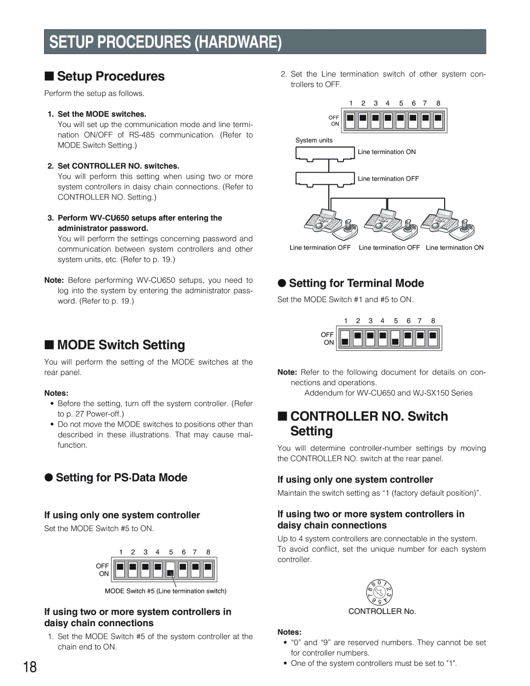
trollers to OFF. |
|
|
|
|
|
|
| |
Perform the setup as follows. |
|
|
|
|
|
|
| |
|
|
|
|
|
|
|
| |
| 1 | 2 | 3 | 4 | 5 | 6 | 7 | 8 |
1.Set the MODE switches.
You will set up the communication mode and line termi- nation ON/OFF of
2.Set CONTROLLER NO. switches.
You will perform this setting when using two or more system controllers in daisy chain connections. (Refer to CONTROLLER NO. Setting.)
3.Perform
You will perform the settings concerning password and communication between system controllers and other system units, etc. (Refer to p. 19.)
Note: Before performing
OFF
ON
System units
Line termination ON
Line termination OFF
Line termination OFF Line termination OFF Line termination ON
●Setting for Terminal Mode
Set the MODE Switch #1 and #5 to ON.
1 2 3 4 5 6 7 8
■MODE Switch Setting
You will perform the setting of the MODE switches at the rear panel.
Notes:
•Before the setting, turn off the system controller. (Refer to p. 27
•Do not move the MODE switches to positions other than described in these illustrations. That may cause mal- function.
OFF
ON
Note: Refer to the following document for details on con- nections and operations.
Addendum for
■CONTROLLER NO. Switch Setting
You will determine
●Setting for PS·Data Mode
If using only one system controller
Set the MODE Switch #5 to ON.
1 2 3 4 5 6 7 8
OFF
ON
MODE Switch #5 (Line termination switch)
If using two or more system controllers in daisy chain connections
1.Set the MODE Switch #5 of the system controller at the chain end to ON.
18
If using only one system controller
Maintain the switch setting as “1 (factory default position)”.
If using two or more system controllers in daisy chain connections
Up to 4 system controllers are connectable in the system. To avoid conflict, set the unique number for each system controller.
9 | 0 | 1 |
8 |
| 2 |
|
| |
7 |
| 3 |
|
| |
6 | 5 | 4 |
| ||
|
|
CONTROLLER No.
Notes:
•“0” and “9” are reserved numbers. They cannot be set for controller numbers.
•One of the system controllers must be set to "1".