Panel Descriptions
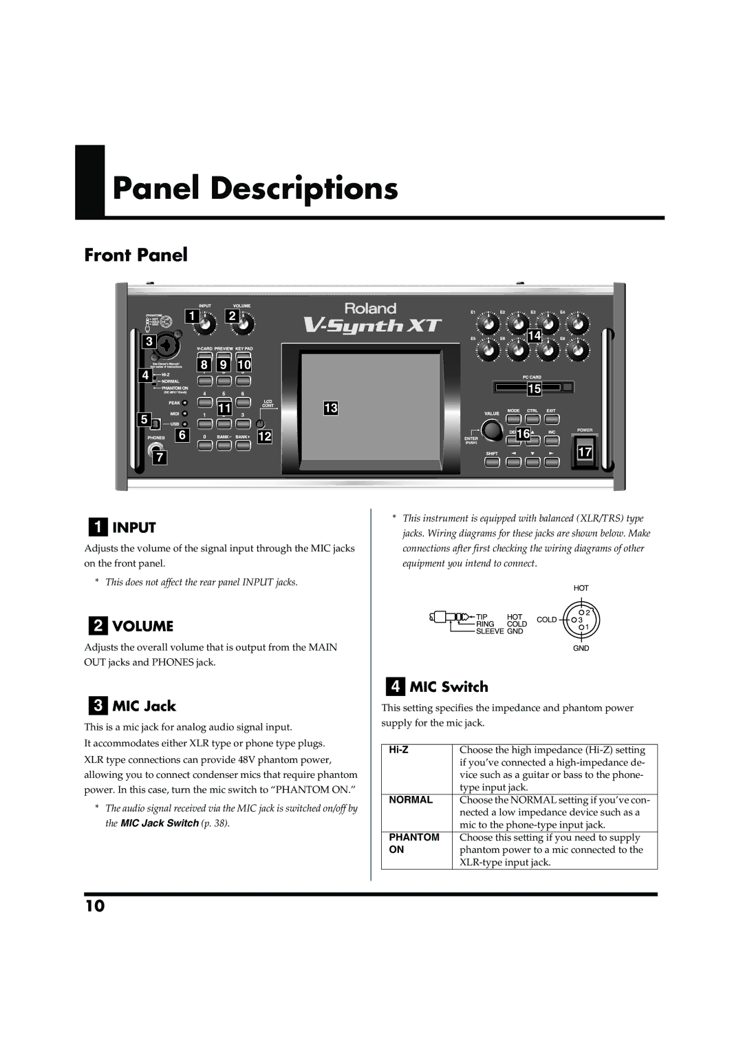
Front Panel
1 | 2 |
|
3 |
|
|
8 | 9 | 10 |
4 |
|
|
5 | 11 |
|
|
| |
6 |
| 12 |
7 |
|
|
14 |
|
15 |
|
13 |
|
16 | POWER |
| |
| 17 |
1INPUT
Adjusts the volume of the signal input through the MIC jacks on the front panel.
* This does not affect the rear panel INPUT jacks.
2VOLUME
Adjusts the overall volume that is output from the MAIN OUT jacks and PHONES jack.
3MIC Jack
This is a mic jack for analog audio signal input.
It accommodates either XLR type or phone type plugs. XLR type connections can provide 48V phantom power, allowing you to connect condenser mics that require phantom power. In this case, turn the mic switch to “PHANTOM ON.”
*The audio signal received via the MIC jack is switched on/off by the MIC Jack Switch (p. 38).
*This instrument is equipped with balanced (XLR/TRS) type jacks. Wiring diagrams for these jacks are shown below. Make connections after first checking the wiring diagrams of other equipment you intend to connect.
4MIC Switch
This setting specifies the impedance and phantom power
supply for the mic jack.
| Choose the high impedance |
| if you’ve connected a |
| vice such as a guitar or bass to the phone- |
| type input jack. |
NORMAL | Choose the NORMAL setting if you’ve con- |
| nected a low impedance device such as a |
| mic to the |
PHANTOM | Choose this setting if you need to supply |
ON | phantom power to a mic connected to the |
|
10