Click Add. Click Add/Remove under Remote Networks and enter:
Remote subnet/netmask: 192.168.1.0 / 255.255.255.0
Click Add. The GRE tunnel between the two networks is now set up. Tunnels may be Disabled, Deleted or Edited from the main table of GRE tunnels. A few further things of note are:
GRE Tunnel Name | The name is arbitrary. |
Remote External Address | This may also be in the form of a DNS name, e.g. a |
| dynamic DNS name. |
Local External Address | This may also be an Internet port alias address, or |
| the address of an secondary Internet connection |
| through the DMZ port. |
Remote subnet/netmask | Multiple networks can be routed through a single |
| GRE tunnel. Add them through Add/Remove under |
| Remote Networks. |
GRE over IPSec
In this example we will bridge the 10.11.0.0 / 255.255.0.0 network between Brisbane and Slough endpoints described in the previous section. For each end, repeat the following steps.
Set up the LAN interface to bridge. Select Network Setup from the left hand menu. For the LAN port’s Configuration, select Change to Bridged LAN. Reboot the unit if prompted to do so.
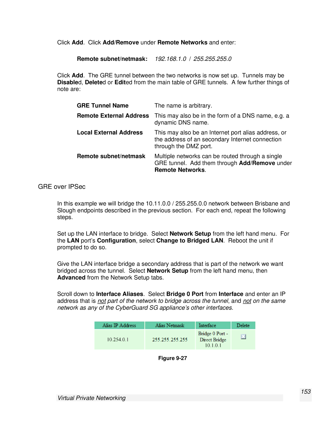
Give the LAN interface bridge a secondary address that is part of the network we want bridged across the tunnel. Select Network Setup from the left hand menu, then Advanced from the Network Setup tabs.
Scroll down to Interface Aliases. Select Bridge 0 Port from Interface and enter an IP address that is not part of the network to bridge across the tunnel, and not on the same network as any of the CyberGuard SG appliance’s other interfaces.
Figure
