M300EU | THEORY OF OPERATION |
(Addendum to M300EU Manual - P/N 04145) |
|
10.2.2. THE A-REF VALVE ASSEMBLY
The
Table |
| ||
|
|
|
|
Mode |
| Valve State | VALVE PORT CONNECTIONS |
SAMPLE |
| Gas stream from Nafion→ Dryer & | 3 Æ 2 |
(Normal State) |
| SAMPLE inlet | |
| Gas stream from CO scrubber | 1 Æ 2 | |
| Gas stream from CO scrubber | 1 Æ 2 | |
SAMPLE DWELL |
| Gas stream from Nafion→ Dryer & | 3 Æ 2 |
| SAMPLE inlet | ||
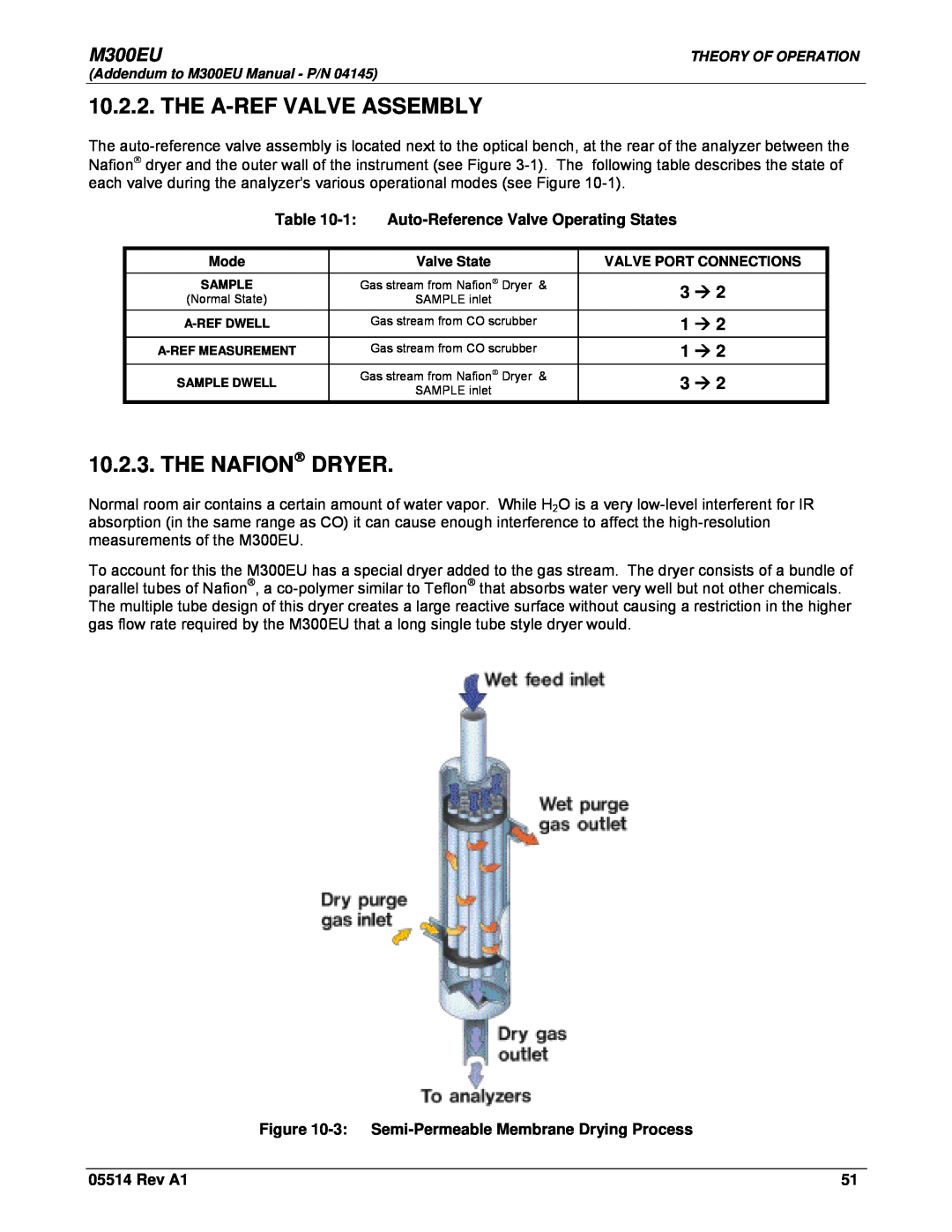
10.2.3. THE NAFION→ DRYER.
Normal room air contains a certain amount of water vapor. While H2O is a very
To account for this the M300EU has a special dryer added to the gas stream. The dryer consists of a bundle of parallel tubes of Nafion®, a
Figure 10-3: Semi-Permeable Membrane Drying Process
05514 Rev A1 | 51 |