THEORY OF OPERATION | M300EU |
| Addendum to M300E/EM Manual P/N 04288 |
10.3.2.3. Status LED’s
This information replaces that found in Sections 10.4.5.5 of the M300E/EM Operators Manual.
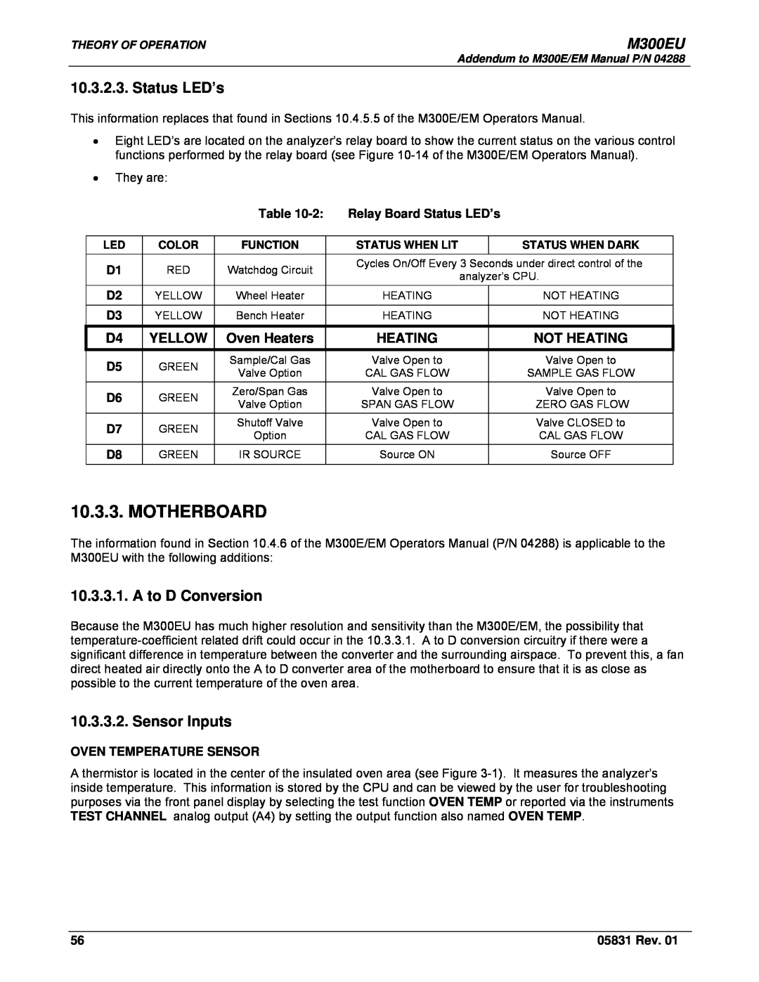
•Eight LED’s are located on the analyzer’s relay board to show the current status on the various control functions performed by the relay board (see Figure
•They are:
|
| Table | Relay Board Status LED’s | ||
|
|
|
|
|
|
LED | COLOR | FUNCTION | STATUS WHEN LIT |
| STATUS WHEN DARK |
D1 | RED | Watchdog Circuit | Cycles On/Off Every 3 Seconds under direct control of the | ||
| analyzer’s CPU. | ||||
|
|
|
| ||
D2 | YELLOW | Wheel Heater | HEATING |
| NOT HEATING |
D3 | YELLOW | Bench Heater | HEATING |
| NOT HEATING |
D4
YELLOW Oven Heaters
HEATING
NOT HEATING
D5 | GREEN | Sample/Cal Gas | Valve Open to | Valve Open to | |
Valve Option | CAL GAS FLOW | SAMPLE GAS FLOW | |||
|
| ||||
D6 | GREEN | Zero/Span Gas | Valve Open to | Valve Open to | |
Valve Option | SPAN GAS FLOW | ZERO GAS FLOW | |||
|
| ||||
D7 | GREEN | Shutoff Valve | Valve Open to | Valve CLOSED to | |
Option | CAL GAS FLOW | CAL GAS FLOW | |||
|
| ||||
D8 | GREEN | IR SOURCE | Source ON | Source OFF |
10.3.3. MOTHERBOARD
The information found in Section 10.4.6 of the M300E/EM Operators Manual (P/N 04288) is applicable to the M300EU with the following additions:
10.3.3.1. A to D Conversion
Because the M300EU has much higher resolution and sensitivity than the M300E/EM, the possibility that
10.3.3.2. Sensor Inputs
OVEN TEMPERATURE SENSOR
A thermistor is located in the center of the insulated oven area (see Figure
56 | 05831 Rev. 01 |
