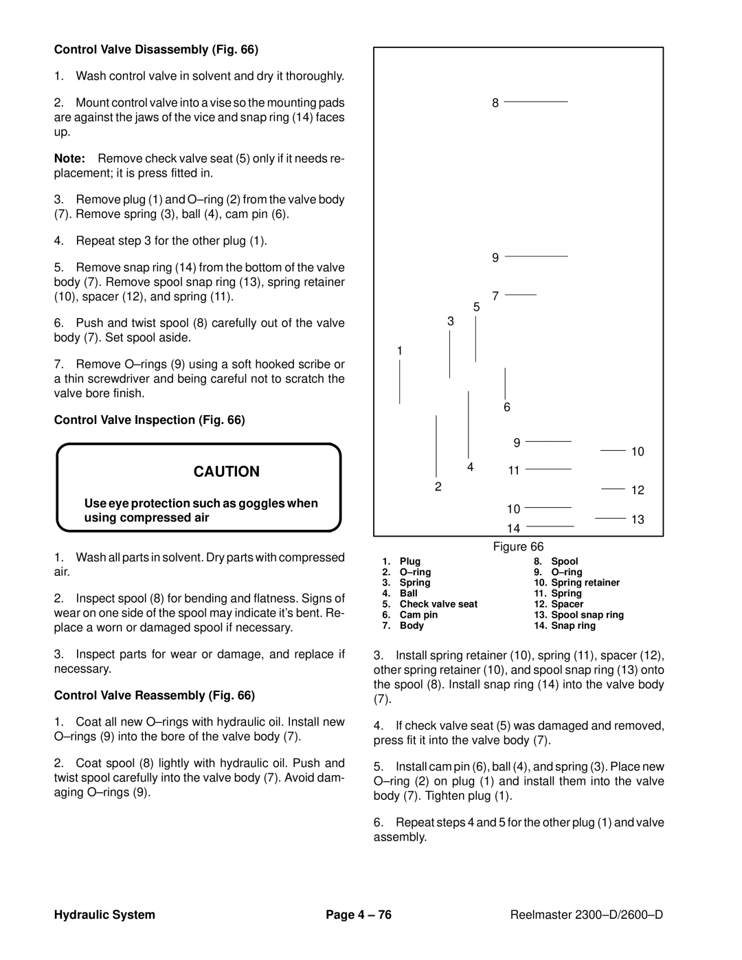
Control Valve Disassembly (Fig. 66)

1.Wash control valve in solvent and dry it thoroughly.

2.Mount control valve into a vise so the mounting pads are against the jaws of the vice and snap ring (14) faces up.

Note: Remove check valve seat (5) only if it needs re- placement; it is press fitted in.

3.Remove plug (1) and O±ring (2) from the valve body

(7). Remove spring (3), ball (4), cam pin (6).

4.Repeat step 3 for the other plug (1).

5.Remove snap ring (14) from the bottom of the valve body (7). Remove spool snap ring (13), spring retainer (10), spacer (12), and spring (11).

6.Push and twist spool (8) carefully out of the valve body (7). Set spool aside.

7.Remove O±rings (9) using a soft hooked scribe or a thin screwdriver and being careful not to scratch the valve bore finish.

Control Valve Inspection (Fig. 66)

CAUTION

Use eye protection such as goggles when using compressed air

1.Wash all parts in solvent. Dry parts with compressed

air.

2.Inspect spool (8) for bending and flatness. Signs of wear on one side of the spool may indicate it's bent. Re- place a worn or damaged spool if necessary.

3.Inspect parts for wear or damage, and replace if necessary.

Control Valve Reassembly (Fig. 66)

1.Coat all new O±rings with hydraulic oil. Install new O±rings (9) into the bore of the valve body (7).

2.Coat spool (8) lightly with hydraulic oil. Push and twist spool carefully into the valve body (7). Avoid dam- aging O±rings (9).

8

9

7

5


3


1


6


9


10


4

11


2


12


10


13


14


Figure 66

1.

Plug

8.

Spool

2.

O±ring

9.

O±ring

3.

Spring

10.

Spring retainer

4.

Ball

11.

Spring

5.

Check valve seat

12.

Spacer

6.

Cam pin

13.

Spool snap ring

7.

Body

14.

Snap ring

3.Install spring retainer (10), spring (11), spacer (12), other spring retainer (10), and spool snap ring (13) onto the spool (8). Install snap ring (14) into the valve body

(7).

4.If check valve seat (5) was damaged and removed, press fit it into the valve body (7).

5.Install cam pin (6), ball (4), and spring (3). Place new O±ring (2) on plug (1) and install them into the valve body (7). Tighten plug (1).

6.Repeat steps 4 and 5 for the other plug (1) and valve assembly.

Hydraulic System

Page 4 ± 76

Reelmaster 2300±D/2600±D

Page 114
Image 114
Toro 2300-D, 2600D service manual Control Valve Disassembly Fig, Control Valve Reassembly Fig

2600D, 2300-D specifications

The Toro 2300-D and 2600-D are industry-leading reel mowers specifically designed for the professional turf care market. Known for their durability, efficiency, and advanced technology, these models provide exceptional cutting performance for golf courses, sports fields, and other high-quality turf applications.

One of the standout features of the Toro 2300-D and 2600-D is their powerful engines. Powered by efficient diesel engines, these mowers deliver robust performance while being fuel-efficient. This capability ensures extended operation periods, allowing grounds crews to maintain pristine conditions across large areas without frequent refuelling stops.

Both models are equipped with Toro’s exclusive DPA (Dual Precision Adjust) cutting system, providing precise cutting heights for optimal turf health. This system allows for adjustments from 1/8 inch to 1 inch, enabling operators to achieve the correct level for various grass types and turf conditions. This level of precision ensures a clean cut and promotes the overall health of the grass.

Another notable characteristic is the ergonomic design, which includes a comfortable operator station to reduce fatigue during extended use. The controls are intuitively located, enabling easy access and operation, and the mower's compact design allows for nimble maneuverability around obstacles, ensuring that every inch of turf can be accurately maintained.

In terms of technology, the Toro 2300-D and 2600-D feature advanced traction control systems that provide excellent grip and stability on slopes and uneven terrain. The lightweight alloy construction of the frame contributes to this stability, giving operators confidence whether they are working on flat surfaces or more challenging landscapes.

Furthermore, these mowers are designed with sustainability in mind. The diesel engines not only offer efficiency but also are compliant with strict emissions standards, making them an environmentally responsible choice for turf maintenance.

The Toro 2300-D and 2600-D also feature a robust maintenance management system that alerts operators of necessary maintenance tasks, promoting longer lifespans for components and enhancing overall performance.

In summary, the Toro 2300-D and 2600-D deliver cutting-edge technologies and features, including powerful engines, versatile cutting systems, ergonomic design, advanced traction control, and sustainability focus. These models represent the pinnacle of reel mower engineering, making them ideal choices for professionals dedicated to maintaining the finest playing surfaces.