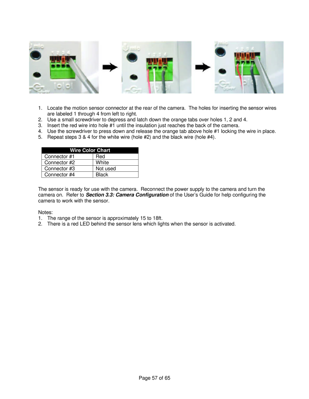
1.Locate the motion sensor connector at the rear of the camera. The holes for inserting the sensor wires are labeled 1 through 4 from left to right.
2.Use a small screwdriver to depress and latch down the orange tabs over holes 1, 2 and 4.
3.Insert the red wire into hole #1 until the insulation just reaches the back of the camera.
4.Use the screwdriver to press down and release the orange tab above hole #1 locking the wire in place.
5.Repeat steps 3 & 4 for the white wire (hole #2) and the black wire (hole #4).
Wire Color Chart
Connector #1 | Red |
Connector #2 | White |
Connector #3 | Not used |
Connector #4 | Black |
The sensor is ready for use with the camera. Reconnect the power supply to the camera and turn the camera on. Refer to Section 3.3: Camera Configuration of the User’s Guide for help configuring the camera to work with the sensor.
Notes:
1.The range of the sensor is approximately 15 to 18ft.
2.There is a red LED behind the sensor lens which lights when the sensor is activated.
Page 57 of 65