Hardware and Connection Setup
Hardware and Connection Setup
This section provides information on setting up the hardware and is organized into setup for each hardware type. Once the setup has been successfully completed, data can be sent to and responses received from the power supply. Select which hardware interface to use and follow the instructions and diagram for that hardware set up.
Configuring Remote Control Using RS-232
To configure remote control using RS-232:
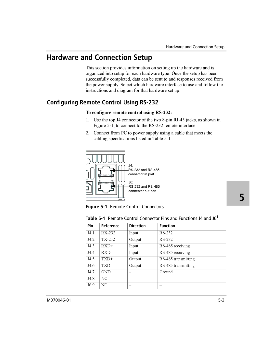
1.Use the top J4 connector of the two
2.Connect from PC to power supply using a cable that meets the cabling specifications listed in Table
J4:
![]() RS-232
RS-232
J6:
![]() RS-232
RS-232
5
Figure | Remote Control Connectors | ||||||
Table | Remote Control Connector Pins and Functions J4 and J61 | ||||||
Pin |
| Reference |
| Direction |
| Function | |
|
|
| |||||
|
|
|
|
|
|
| |
J4.1 |
|
| Input |
| |||
J4.2 |
|
| Output |
| |||
J4.3 |
| RXD+ |
| Input |
| ||
J4.4 |
| RXD– |
| Input |
| ||
J4.5 |
| TXD+ |
| Output |
| ||
J4.6 |
| TXD– |
| Output |
| ||
J4.7 |
| GND |
| – |
| Ground | |
J4.8 |
| NC |
|
| – |
| – |
J6.9 |
| NC |
|
| – |
| – |
|
|
|
|
|
|
|
|