|
| Figures |
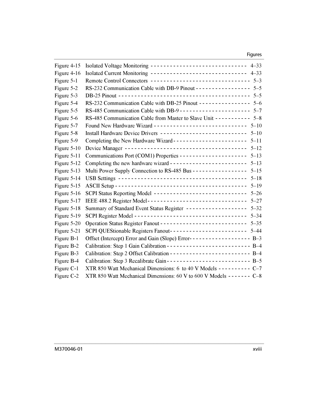
Figure | Isolated Voltage Monitoring - - - - - - - - - - - - - - - - - - - - - - - - - - - - - - | |
Figure | Isolated Current Monitoring - - - - - - - - - - - - - - - - - - - - - - - - - - - - - - | |
Figure | Remote Control Connectors - - - - - - - - - - - - - - - - - - - - - - - - - - - - - - | - |
Figure | - | |
Figure | - | |
Figure | - | |
Figure | - | |
Figure |
| - |
Figure | Found New Hardware Wizard - - - - - - - - - - - - - - - - - - - - - - - - - - - - - | |
Figure | Install Hardware Device Drivers - - - - - - - - - - - - - - - - - - - - - - - - - - - | |
Figure | Completing the New Hardware Wizard - - - - - - - - - - - - - - - - - - - - - - - | |
Figure | Device Manager - - - - - - - - - - - - - - - - - - - - - - - - - - - - - - - - - - - - - - | |
Figure | Communications Port (COM1) Properties - - - - - - - - - - - - - - - - - - - - - | |
Figure | Completing the new hardware wizard - - - - - - - - - - - - - - - - - - - - - - - - | |
Figure | Multi Power Supply Connection to | |
Figure | USB Settings - - - - - - - - - - - - - - - - - - - - - - - - - - - - - - - - - - - - - - - - | |
Figure | ASCII Setup - - - - - - - - - - - - - - - - - - - - - - - - - - - - - - - - - - - - - - - - - | |
Figure | SCPI Status Reporting Model - - - - - - - - - - - - - - - - - - - - - - - - - - - - - | |
Figure | IEEE 488.2 Register Model- - - - - - - - - - - - - - - - - - - - - - - - - - - - - - - | |
Figure | Summary of Standard Event Status Register - - - - - - - - - - - - - - - - - - - | |
Figure | SCPI Register Model - - - - - - - - - - - - - - - - - - - - - - - - - - - - - - - - - - - | |
Figure | Operation Status Register Fanout - - - - - - - - - - - - - - - - - - - - - - - - - - - | |
Figure | SCPI QUEStionable Registers Fanout- - - - - - - - - - - - - - - - - - - - - - - - | |
Figure | Offset (Intercept) Error and Gain (Slope) Error- - - - - - - - - - - - - - - - - - | - |
Figure | Calibration: Step 1 Gain Calibration - - - - - - - - - - - - - - - - - - - - - - - - - | - |
Figure | Calibration: Step 2 Offset Calibration - - - - - - - - - - - - - - - - - - - - - - - - | - |
Figure | Calibration: Step 3 Recalibrate Gain - - - - - - - - - - - - - - - - - - - - - - - - - | - |
Figure | XTR 850 Watt Mechanical Dimensions: 6 to 40 V Models - - - - - - - - - | - |
Figure | XTR 850 Watt Mechanical Dimensions: 60 V to 600 V Models - - - - - - | - |
xviii |
