Remote Operation
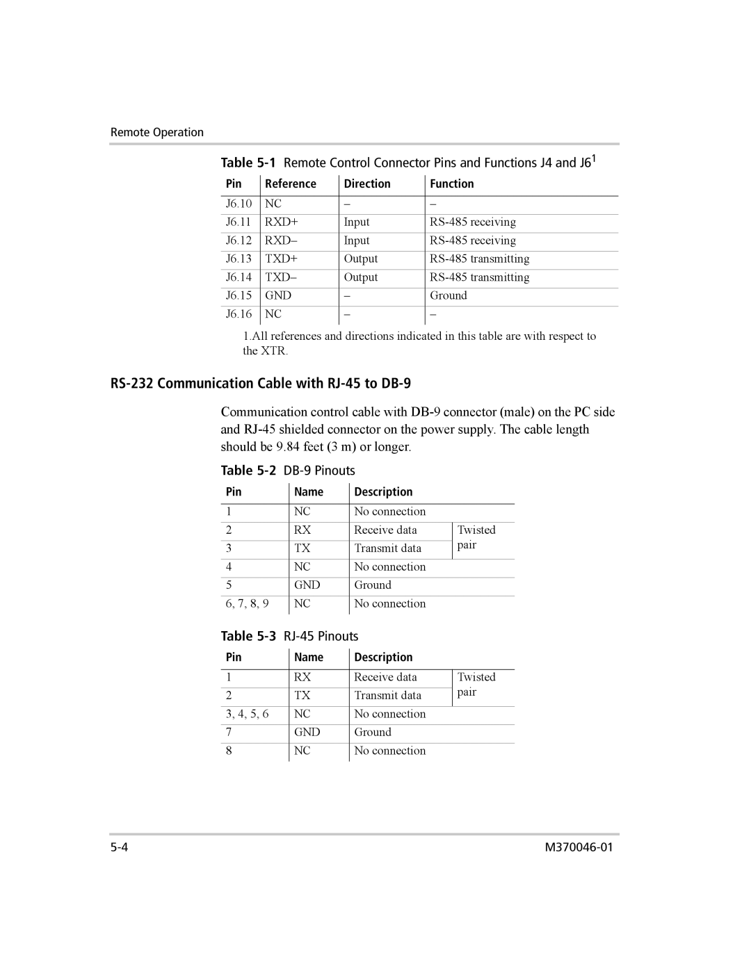
Table 5-1 Remote Control Connector Pins and Functions J4 and J61
Pin | Reference | Direction | Function |
|
|
|
|
J6.10 | NC | – | – |
J6.11 | RXD+ | Input | |
J6.12 | RXD– | Input | |
J6.13 | TXD+ | Output | |
J6.14 | TXD– | Output | |
J6.15 | GND | – | Ground |
J6.16 | NC | – | – |
|
|
|
|
1.All references and directions indicated in this table are with respect to the XTR.
RS-232 Communication Cable with RJ-45 to DB-9
Communication control cable with
Table |
|
| |||
Pin |
| Name |
| Description |
|
|
|
| |||
|
|
|
|
|
|
1 |
| NC |
| No connection |
|
2 |
| RX |
| Receive data | Twisted |
|
|
|
|
| pair |
3 |
| TX |
| Transmit data | |
4 |
| NC |
| No connection |
|
5 |
| GND |
| Ground |
|
6, 7, 8, 9 |
| NC |
| No connection |
|
|
|
|
|
|
|
Table |
|
| |||
Pin |
| Name |
| Description |
|
|
|
| |||
|
|
|
|
|
|
1 |
| RX |
| Receive data | Twisted |
|
|
|
|
| pair |
2 |
| TX |
| Transmit data | |
3, 4, 5, 6 |
| NC |
| No connection |
|
7 |
| GND |
| Ground |
|
8 |
| NC |
| No connection |
|
|
|
|
|
|
|
