GNS 530A
Page
Initial Release
Updated per Main SW
Record of Revisions
Revision Date of Revision Description
Copyright
Table of Contents
MESSAGES, ABBREVIATIONS,
GNS 530A Pilot’s Guide and Reference
GNS 530A Pilot’s Guide and Reference
Limited Warranty
Warranty
Blank
Section Introduction
Standard Package
KEY and Knob Functions
Right-hand Keys and Knobs
Left-hand Keys and Knobs
Blank Direct-to
Bottom Row Keys
Overview
Powering up the GNS
Flight plan features Section IFR procedures Section
Takeoff Tour
Press the ENT Key
Instrument Panel Self-test
Acknowledging the database information
Setting fuel on board to full if not provided by sensor
Viewing the Checklists
Press the MSG Key again
Satellite Status
Viewing a system message
Returning to the previous page after viewing a message
Placing the standby frequency in the active field
Selecting COM and Vloc Frequencies
Changing the standby communication frequency
Changing the standby Vloc frequency
Selecting the desired NAV
Groups
NAV Pages
Groups
Selecting a direct-to destination
Map
Direct-to Navigation
Press and hold the CLR Key Figure
Default NAV
Selecting the Default NAV
Changing the data fields
NAV/COM
22 Airport Window
Selecting a communication or navigation frequency
Selecting an approach, departure, or arrival
IFR Procedures
To display the Procedures Page -23, press the Proc Key
Displaying a list of nearby airports
Nearest Nrst Pages
Displaying the Nrst pages
Turn the small right knob to select the desired Nrst
Press the Direct-toKey Press the ENT Key Figure
Viewing additional information for a nearby airport
Viewing additional airspace information
Nearest Nrst Airspace
Viewing an airspace alert message
Press the MSG Key again to return to the previous display
Creating a new flight plan
Flight Plans FPL
35 Flight Plan Catalog Page Menu
Activating the new flight plan
Section COM
Volume
COM Window and Tuning
Squelch
Standby Frequency
Selecting a COM frequency
Selecting a COM frequency for a nearby airport
Auto-Tuning
Nearest Artcc
Selecting a COM frequency for any airport in the flight plan
Selecting a COM frequency for any airport in the database
Quickly tuning and activating
Emergency Channel
Stuck Microphone
Blank
Selecting the desired page within the group
Main page Groups
Section NAV Pages
Selecting the desired page group from any
NAV page Group
Default NAV
Adjusting the Map scale
Quickly selecting the Default NAV Page from any
Selecting a different data item for any data field
Selecting Desired On-Screen Data
Dual Unit Considerations
Restoring Factory Settings
Restoring all six data fields to factory default settings
Enabling or disabling the auto zoom feature
Selecting a map range
MAP
Map Detail Level
Quickly decluttering the Map Display
Press the CLR Key to exit the information pages
Map Panning
Selecting the panning function and panning the Map Display
Press the ENT Key to display an options menu Figure
Map Direct-to
Airspace Information on the Map
Map
Map Setup
Displaying the Map Page Menu
Press the ENT Key to accept the selected option Figure
To enable/disable automatic zoom
Changing the map orientation
Section NAV Pages
To turn the data fields off/on
Distance Measurements
Adding Data Fields to the Map
Measuring bearing and distance between two points
Press the small right knob to remove the cursor
Restoring the factory default settings
Clearing On-Screen Weather Data
Changing a data field
Terrain
Selectable Display Settings
Terrain
Select the Terrain Page and press the Menu Key
Displaying a 120˚ view
Changing the display range
Showing or hiding aviation data
Enabling Terrain
Inhibit Mode
Terrain Symbols
Inhibiting Terrain
Taws
Taws
Press the ENT Key. The Taws system is functional again
Inhibiting Taws
Enabling Taws
Taws Manual Test
Taws Symbols
Manually testing the Taws system
Press the small right knob to activate the cursor
NAV/COM
To return to the NAV/COM Page, press the ENT Key
Scrolling through the list of frequencies
Viewing usage restrictions for a frequency
Sky View GPS Receiver Status
Satellite Status
By an altitude serializer
Using satellite data
GPS Receiver Status Messages
Should be in view
Press the Direct-toKey, followed by the ENT Key twice
Overview
Section DIRECT-TO Navigation
Selecting a direct-to destination by facility name or city
Selecting a Destination by Facility Name or City
Selecting a direct-to destination from the active flight plan
Selecting a Destination from the Active Flight Plan
Selecting an on-screen waypoint as a direct-to destination
Selecting the Nearest Airport as a Direct-to Destination
Shortcuts
Selecting a nearby airport as a direct-to destination
Selecting a direct-to destination from the Map
Selecting a Direct-to destination from the Map
Press the Direct-to Key followed by the ENT Key twice
Manually defining the direct-to course
Cancelling Direct-to Navigation
Cancelling a direct-to
Specifying a Course to a Waypoint
Section Flight Plans
Flight Plan Catalog
Adding a waypoint to an existing flight plan
Flight Plan Editing
Changing the comment line for an existing flight plan
Deleting a waypoint from an existing flight plan
Activating an existing flight plan in reverse order
Activating Flight Plans
Inverting Flight Plans
Activating an existing flight plan
Deleting a flight plan
Copying Flight Plans
Deleting Flight Plans
Copying a flight plan to another flight plan catalog location
14 Crossfill GNS 530A Pilot’s Guide and Reference
Flight Plan Catalog Options
Sorting the catalog listing by number or comment
Deleting all flight plans
Options shown in -1 are available for Active Flight Plan
Accessing the Active Flight Plan Menu
Active Flight Plan
Active Flight Plan Options
Active Flight Plan Page Menu Options
Activating a flight plan along a specific leg
Changing a data field on the Active Flight Plan
23 Active Flight Plan Page Menu
Selecting a departure for the departure airport
With ‘Load?’ highlighted, press the ENT Key
29 Active Flight Plan Page Menu
Press the CLR Key to display a confirmation window Figure
Removing a waypoint using the CLR Key
Press the ENT Key to select the WPT Page Group
Reviewing a procedure while viewing a flight plan
Activating a specific leg of the active flight plan
With ‘Activate?’ highlighted, press the ENT Key
Blank
Press the Proc Key to display the Procedures
Section Procedures
‘GPS’ Designations
Activating an approach
NON-PRECISION Approach Operations
Activating the approach, with vectors to final
Approaches with Procedure Turns
NAV/COM
Refer to -12 for the following steps
Flying the Procedure Turn
Turn to the final approach course
Fly the outbound course
Refer to -17 for the following steps
Flying the Missed Approach
23 ‘Hold Teardrop’ Annunciation
Flying an Approach with a Hold
Refer to -27 for the following steps
Refer to -29 for the following steps
29 Approach Mode
31 Final Approach
Flying a DME Arc Approach
Refer to -35 for the following steps
36 Procedures
Refer to -38 for the following steps
38 Approach Mode
Selecting ‘VECTORS’ from the Transitions Window
Activating vectors-to-final from the Procedures
Vectors to Final
Flying the Vectors Approach
42 Procedures
Refer to -46 for the following steps
When approaching the FAF, a waypoint alert
ATC instructs the pilot to turn right to a heading
Course From Fix Flight Plan Legs
50 Waypoint Alert, Default NAV
PMD VOR
55 Waypoint Alert
Departure runway in this example
On selecting departures
59 Waypoint Alert
ILS Approaches
Selecting an ILS Approach
Acknowledge the message
As mentioned, the Vloc receiver must be
Used for this approach. Press the ENT Key to
Flying the ILS Approach
Turn to track the ILS approach course
Refer to -68 for the following steps
70 CDI Scale Transition
72 Waypoint Alert
Points to Remember for Localizer-based Approaches
Points to Remember for ALL Approaches
Localizer frequency must be active to use Vloc guidance
Blank
Quickly selecting a WPT
WPT page Group
Section WPT Pages
Turn the large right knob to select the next character field
Entering a waypoint identifier
Entering a waypoint facility name or city location
First Facility for Charlotte
Duplicate Waypoints
Selecting a waypoint identifier from a list of duplicates
Airport Location
Selecting an Airport Location Page Menu Option
Airport Location Page Options
Elevation In feet or meters
Radar Radar coverage Yes or No
Displaying information for each additional runway
Airport Runway
Selecting an Airport Runway Page Menu Option
Adjusting the range of the map image
Airport Runway Page Options
14 111.55 Highlighted
Airport Frequency
To return to the Airport Frequency Page, press the ENT Key
Atis Asos Awos
Scrolling through the available approaches and transitions
Airport Approach
Airport Frequency Page Options
Selecting an Airport Frequency Page Menu Option
20 Approach Window
Airport Approach Page Options
Scrolling through the available arrivals
Airport Arrival
Loading an approach from the Airport Approach
24 Arrivals Window
Scrolling through the available departures
Loading an arrival procedure from the Airport Arrival
Airport Departure
Airport Arrival Page Options
Press the ENT Key. The cursor moves to the runway field
Loading a departure procedure from the Airport Departure
Airport Departure Page Options
Freq Frequency in kilohertz kHz
Intersection
NDB
Following descriptions and abbreviations are used
Selecting a VOR frequency from the VOR
VOR
Creating User Waypoints
User Waypoint
Press the small right knob to remove the flashing cursor
Press the ENT Key to accept the selected position
Capturing and saving the present position as a user waypoint
Creating User Waypoints from the Map
42 Position Field Selected
Modifying User Waypoints
Viewing a list of all user waypoints
User Waypoint Page Options
Select the User Waypoint List, as described in this section
User Waypoint List
Press the small right knob to return to the User Waypoint
Deleting a user waypoint
Deleting a user waypoint from the User Waypoint List
Renaming a user waypoint from the User Waypoint List
50 User Waypoint List Page Menu
Deleting all user waypoints from memory
Blank
Quickly selecting a Nrst
Nrst page Group
Section Nrst Pages
Nearest FSS
Navigating to a Nearby Waypoint
Nearest Airport
Frequency Moved to Active Field
Desired Airport Highlighted
Nearest Intersection
Nearest VOR
Nearest NDB
Viewing additional information for a nearby VOR
Quickly tuning a VOR’s frequency from the nearest VOR
Nearest User Waypoint
Nearest Center Artcc
Nearest Flight Service Station FSS
20 FSS Field Selected
Press the MSG Key again to return to the previous
Nearest Airspace
Shows ‘Inside of airspace’
Listed on the Nearest Airspace
Viewing additional details for an airspace
Press the COM Flip-flopKey to activate the selected frequency
Unspecified
See Chart Surface
Prohibited Restricted
Training
To select a VOR/localizer/ILS frequency
Ident Audio and Volume
Vloc Window and Tuning
Section Vloc Receiver
To select a Vloc frequency from the VOR Page or Nearest VOR
Vloc Ident Window
Frequency Highlighted on Nrst VOR
Tuning the Vloc when an approach is active
Highlight ‘Load?’
CDI Key
Turn the small right knob to select the desired AUX
AUX page Group
Section AUX Pages
Quickly selecting an AUX
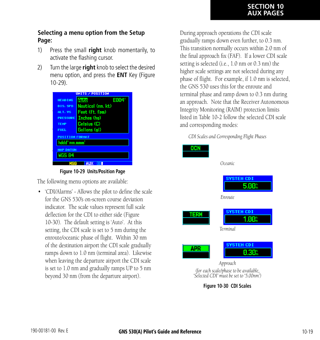
Following menu options are available
Flight Planning
Selecting a menu option from the Flight Planning
10-3
Performing fuel planning operations
Flight Planning Page Fuel Planning
Performing trip planning operations
Flight Planning Page Trip Planning
Calculating density altitude, true airspeed, and winds aloft
Flight Planning Page Density Alt/TAS/Winds
Entering a scheduled message
Flight Planning Page Scheduler
Deleting a scheduled message
Flight Planning Page Crossfill
Editing a scheduled message
flashing cursor highlights the first message field
10-9
15 Utility
Utility
16 Trip Statistics
Selecting a menu option from the Utility
Creating a checklist
Utility Page Checklists
Deleting a checklist or all checklists
Executing a checklist
Editing a checklist
Inserting a checklist step into an existing checklist
Viewing, using, or resetting the generic timer
Utility Page Flight Timers
Copying a checklist
Sorting the checklists by name or entry
Viewing, using, or resetting total trip time
Recording or resetting the departure time
Predicting Raim availability
Resetting trip statistics readouts
Utility Page Trip Statistics
Utility Page Raim Prediction
Utility Page Database Versions
Utility Page Software Versions
Utility Page Terrain Database Versions
Setup
29 Units/Position
Selecting a menu option from the Setup
For example, if the buffer is set at 500 feet,
Raim Protection
Auto oceanic ±5.0 nm or Auto Enroute
±0.3 nm or Auto Approach
31 Restricted Alarm Window
Setup Page CDI/Alarms
Changing the maximum CDI scale
Setup Page CDI Scale/Alarms
Changing the ILS CDI scale
Setting the arrival alarm and alarm distance
Changing the units of measure
Setup Page Units/Position
Setting the magnetic variation
Press the ENT Key to accept the selected format
Changing the position format
Displaying the map datum
Mgrs Military Grid Reference System
Press the ENT Key to accept the selected offset
Setup Page Date/Time
Setting the local time
Displaying local time or UTC
Changing the backlighting intensity
Setup Page Display Backlight
Setup Page Nearest Airport Criteria
Setting the minimum runway length and runway surface
Abbreviation Data Type
Setup Page Data Field Configuration
Configuring the Auxiliary Data Field
With ‘Restore Defaults?’ highlighted, press the ENT Key
Setup Page COM Configuration
Setting the COM channel spacing
10-30
Press the Vnav key
Section Vertical Navigation
Displaying the Vertical Navigation
Target Altitude Selected
Creating a vertical navigation profile
11-3
Disabling/enabling the vertical navigation Vnav messages
Restoring the factory default Vnav settings
Limitations
System must have a valid 3-D GPS position solution
Introduction
Operating Criteria
Baro-Corrected Altitude
Using Terrain
Terrain Alerting
Altitude
Unlighted Obstacle
Terrain Alerts
When an alert is issued, visual annunciations are displayed
Terrain Failure None Terrain Inhibited Terrain Not Available
Alert Type Annunciation Pop-Up Alert
Alert Type
Shows system status annunciations that may also be issued
Is displayed in the Terrain annunciator field
Premature Descent Alerting
Terrain not Available Alert
Terrain Failure Alert
Database Versions
General Database Information
Database Coverage Area
Database Updates
Terrain/Obstacle Database Areas of Coverage
Updating terrain/obstacle databases
Section Taws
Taws Alerting
Using Taws
AGL
1000’
Taws Annunciation Field
Taws Alerts
RTC Warning
Indicates the default configuration
Pop-Up Alert Aural Message
Phase of Flight
Forward Looking Terrain Avoidance
Functional again
Taws Inhibit
Excessive Descent Rate Alert
Negative Climb Rate NCR Alert Criteria
Negative Climb Rate After Takeoff Alert NCR
Taws Failure Alert
‘FIVE-HUNDRED’ Aural Alert
Taws not Available Alert
Database Information for Taws
13-12
TIS Operation
Traffic Information Service TIS Interface
Section Additional Features
Above the requesting aircraft Figure
TIS Operational Procedures
TIS Limitations
14-3
Traffic Type
TIS Symbology
TIS Audio Alerting
TIS Traffic data is displayed on the Traffic Page Figure
Traffic
TIS Traffic Display Status and Pilot Response
Traffic Coasting Banner Age Indicator
10 ‘Standby’ Message
Traffic Warning Window
Changing the display range on the Traffic
Traffic Page Display Range
‘TA’ annunciation
Displaying Thumbnail Traffic on the Map
Thumbnail Traffic on Map
Configuring TIS traffic on the Map
TA only Only traffic advisories are displayed on the Map
GTX 330 has failed
Highlighting TIS Traffic Using Map Page Panning
Power-Up Test
Activating the panning feature and panning the map display
Press the ENT Key to confirm
Flight Procedures
Manual Override
After Landing
Introduction
Weather Data Link Interface
Nexrad Limitations
Weather Products
Nexrad Description
Nexrad Abnormalities
Display DBZ Rain Snow Source of Nexrad Echo
Nexrad Intensity
Requesting Nexrad data from the Data Link
Requesting Nexrad Data
Follow the preceding steps 4
Data Received Message GDL 49 Only
Requesting Nexrad data from the Map
Customizing the Nexrad data on Weather
Customizing Nexrad Data on the Weather
To display Nexrad Data on the Weather
Press the small right knob
Pattern
Customizing Nexrad Data on the Map
Customizing the Map
Three methods of selecting the Airport Location
Request Shortcuts
Data Link Request Log Page is displayed Figure
Sending Position Reports GDL 49 Only
Data Link Request Log Page GDL 49 Only
Viewing the Data Link Request Log
Select the Data Link Page from the AUX Page Group
Requesting Graphical Metars
Requesting graphical Metars from the Data Link
Metar Request Page has the following user- selectable fields
Displaying graphical Metars on the NAV Weather
Displaying graphical Metars on the NAV Weather
Requesting graphical or textual Metars from the Map
Select the Map
Displaying the Weather Legend
Weather Legend
Displaying Textual Metars
Displaying Wind Data
Displaying Temperature/Dewpoints
View the Data Link Status
Troubleshooting
Monitoring the Data Link
‘Data Link has
During power-up
‘ ’
Has been lost
Quality is ‘0’
Standard Aviation Forecast Abbreviations
‘Satellite
View’
Ceiling and Visibility Flight Rules
Metar Graphics
METARs
Graphics
Blank Unknown
Winds
Wind Speed
Temp Dewpoint Display Ranges
Temperature Dewpoints
14-32
Detection and Exclusion
Fault Detection
Fault Detection Exclusion
Terminal and En Route Area Navigation Rnav Operations’
PRE-DEPARTURE Verification of FDE
Messages ABBREVIATIONS, & NAV Terms
Messages
COM transmitter power has been reduced
FPL is full remove unnecessary waypoints
Data transfer cancelled crossfill is busy
Data transfer cancelled version mismatch
Nm of an arrival airport, when an approach is loaded
Not receiving input data on 429 Channel
Select appropriate frequency for approach
Unit configuration has changed The GNS
Persists, contact a Garmin dealer for assistance
Fpm
Abbreviations
Heading Millibars of Pressure Inches of Mercury Med Medium
Feet
Localizer
Glideslope Lrg Large Gallons Liters
Temperature
Procedures
Power
Total Air Temperature
ALT altitude Height above mean sea level MSL
Expressed as a horizontal position error in feet or meters
Navigation Terms
16-13
16-14
To insert the NavData or Terrain Data card Figure A-2
Appendix a Data Card USE
Figure A-3 Swing Arm Handle Operation
To remove the NavData or Terrain data card Figure A-2
Unit Size 25’W x 11.00’D x 4.60’H
Unit Weight Pounds installed 3.9 kg
Temperature
Update Rate Once per second, continuous Accuracy
Appendix B Specifications
Appendix C MAP Datums
What is RAIM, and how does it affect approach operations?
What does the OBS key do and when do I use it?
Can I file slant Golf ‘/G’ using my GPS?
Annunciator
Figure C-4 ‘SUSP’ Annunciation
How do I fly the GPS with an autopilot and DG heading bug?
Enroute/Oceanic
When does the CDI scale change, and what does it change to?
flashing turn advisory ‘TURN to ###’
CDI Comparison GPS vs. VOR
Index
GPS
Map orientation 3-10
Index
Index
Blank
Page
503.391.3411 f