Protect PV.630
Page
Page
Page
Protect PV.630
Operating instructions
AEG Power Solutions GmbH
Table of Contents
Monitoring Systems, Messages and Faults
System Function
Interfaces
Graphical Display and Operation Unit
Information on How to Use these Instructions
Warranty
General Information
Validity
Target Groups
Explanations of Target Groups
Obligations of the Equipment Operator
Handling
Skilled Personnel Skills and Trainings
Storing Instructions
Obligations of skilled personnel
Explanation of Symbols
Explanation of Symbols and Safety Instructions
Symbol Meaning
Safety Instructions
Signal Words Used
Hazard Symbols Used
Symbol Meaning for skilled personnel
Signs Containing Orders for Personal Protective Equipment
Safety Awareness
Emergency Procedure e.g. in the Event of a Fire
Abbreviations
Particular Dangers associated with Photovoltaic Systems
Crystalline silicon cells
Thin-film cells
Lightning protection
Safety Signs and Warning Notices on the Equipment
Safety and Protection Devices for the Equipment
System stop switch
Protective Covers
Guard
Lockable Equipment Doors
Residual Hazards
Electrical Hazards
Risks Due to Moving Parts
Fire-Related Risks
Water in electrical equipment
Risk of injury due to rotating fans
Risks from Maintenance and Repair Work
Risks due to Loss of Control
Product Description
Product Details
Important information about equipment documenta- tion
Safety
Dimensions and Views
Appropriate Use
Standards, Directives and CE Mark
Inappropriate Use
Nameplate
Technology
Operating Elements
System Description
Operating Modes
Individual Operation
Partner Operation
System Function
Description of Sequence Control
OFF Status
Waiting for Feed Conditions Status
Operation Status
Waiting Status
Fault Status
Night Status
Sequence Control During the Course of the Day
Early morning
Day
Evening
Later in the evening
Night
Inverter stack switch-on time
Permissible voltage dip after switching on the stack
Power limit value for shutdown, delay time for shutdown
Sequence Control Parameters
Description of Fan Control General
Fan Control, Cabinet Fan
Cabinet Fan Control Parameters
Fan Control, Inverter Stack Fan
Igbt temperature limit value for switching off the fan
Igbt temperature limit
Parameters of Inverter Stack Fan Control
Insulation Monitoring and Earthing of PV Cells General
Maintenance mode
Operation with Thin-Film Solar Cells
General
Sequence control
Insulation Monitoring in Partner Operation
Insulation Monitoring Parameters
MPP Tracker
Linked Operation
Change of status to separate operation
Single Operation
Change of status to linked operation
Linked Operation in the Event of a Fault
Partner Operation During the Course of the Day
Extended operating mode
Load threshold for connecting the INV
Partner Operation Parameters
Later that morning
Monitoring Systems, Messages and Faults
Parameters of the Extended operating mode
Power rating for normal feed-in capacity
Power rating for increased feed-in capacity
Protect PV.630 Operating Instructions
Table of Faults
Temperature monitoring systems
Can I/O monitoring systems Fault/Message
Unit Monitoring Systems Fault/Message
DC voltage monitoring systems Fault/Message
Interfaces
Communication Interface
Technical Data MultiCom CCC hardware data assembly A29.1
Communication data port 1
Communication data port 2
Communication data port 3
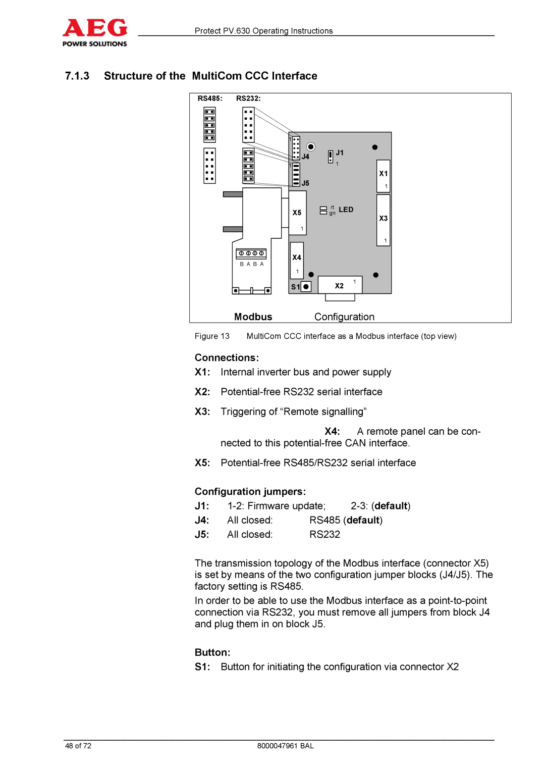
Configuration jumpers
Structure of the MultiCom CCC Interface
Connections
Button
Description of serial interfaces
Port 2 X5 RS485 pin assignment default
Shield connection of the RS485 bus line
Controller Area Network can at
Port 2 X5 RS232 pin assignment
Port 3 X4 can pin assignment
Configuration Preparations
Configuration
Setting the terminal program
Carriage return or Enter key
Configuring the Modbus Protocol
Data protocol configuration
Configuring Modbus Data Transmission
Modbus/JBus data transmission configuration
Network Connection
COM Server General
Structure of the COM Server
Installation of the COM Server
Network Integration Configuration
Configuration of the Virtual COM Port
Technical data
Remote Signalling
Structure
Following default signals are used for remote signalling
Graphical Display and Operation Unit
DOU
Signalling
Acoustic signal generator
Keyboard Operation
LEDs
Possible symbol keys and their function
Start-up
Menu Structure Menu Tree
Main Menu
Operating Display
Operating display Normal operation
Examples of possible displays
Example of operating display
Solar radiation is too low, the inverter is in standby mode
Monthly data t = day 1 31 for the last 12 months
Example of yearly overview
Menu
Status/Measured Values
Blocking
Menu Inverter
Fault History
Settings
Service
Information
Installation and Start-up
80000047963 BAL
Start-up
Connection Work
Isolating Solar Inverters
Safety
General Information
Transport, Storage and Installation
Installation Site Requirements, Operating Area
Packaging
Storage
Air vents on the system 1=supply air, 2=exhaust air
Risk of accident due to suspended loads
Using a Crane to Transport and Install the System
Preparations
Transporting the Equipment
Risk of accident due to transport with industrial trucks
Using a Forklift or Lowlift Truck to Transport the System
Preparation
Transporting a system using industrial truck
Installing, Aligning, Attaching
Bottom attachment 80000047963 BAL
Tightening Torque Values for Screw Connections
Installation without control cabinet doors
Connection Work
System not installed correctly
Power terminals
External Connections
Control/Monitoring terminals
Cables are connected as follows
Start-up
Start-up Preparations
Before connecting the AC voltage, check
Prerequisites
Connection of AC Voltage
Medium voltage Switchgear not connected correctly
Right bridge block
Auxiliary power supply via external circuit
After connecting the DC voltage
Field rotation fault fault message
Other fault indications
Connection of DC Voltage
Isolation Procedure
Isolating Solar Inverters
Maintenance and Servicing
Protect PV.630 Maintenance and Servicing
Fault Messages
General Information
Maintenance and Repair
Scope of the Recommended Measures
Inspection
Visual Inspection
View of cabinet without doors 80000047962 BAL
Diagnostic Functions
Reading Out the Memory
Removing Accumulated Dust
Obligation to Keep a Written Record
Functional Test
Isolating Solar Inverters
Cleaning and Checking the Protection Devices
Maintenance
Checking the Monitoring System
System Stop
Additional Work
Repair
Installing the fan
Removing and Installing the Fans
Removing the fan
Power Section
Spare Parts and Customer Service
Fault Messages
Component
Page
Protect PV.630
Page
CEA
Page
X3UVWPE
Page
1000003063
Page
Peinv
Page
F83
Page
A29.1 A27 A20
Page
1000003063 en